Device socket

a technology of plug-in connectors and sockets, applied in the field of plug-in connectors, can solve the problems that the length and height compensation of non-standardised plug-in connectors cannot be solved via the device socket, and achieve the effect of easy replacemen

Active Publication Date: 2015-12-31
HARTING ELECTRIC GMBH & CO KG
View PDF1 Cites 1 Cited by
  • Summary
  • Abstract
  • Description
  • Claims
  • Application Information

AI Technical Summary

Benefits of technology

[0010]The device socket according to the invention provides length and height compensation without requiring more installation space therefor.
[0017]Such a device socket can be adjusted in such a way that various non-standardised conventional plugs can be plugged in. Such a device socket enhances the overall quality of the device because the customer no longer needs to make sure during operation that they have the proper plug. Moreover, such a socket will not be damaged if an attempt is made to plug in a non-matching plug. Finally, the device socket can be adapted to the respective plug-in connector.
[0019]The seal is a particularly low-cost component of the device socket. It is therefore easily possible to store a relatively large number of different seals with a different vertical positioning of the electronic component.

Problems solved by technology

So far, experts were of the opinion that the problem of length and height compensation of non-standardised plug-in connectors cannot be solved via the device socket, because the devices that have the socket integrated therein do not provide enough space, so-called installation space.

Method used


Image

  • Device socket
  • Device socket
  • Device socket

Examples


Embodiment Construction

[0033]An embodiment example of the invention is shown in the drawings and will be explained in more detail below, wherein:

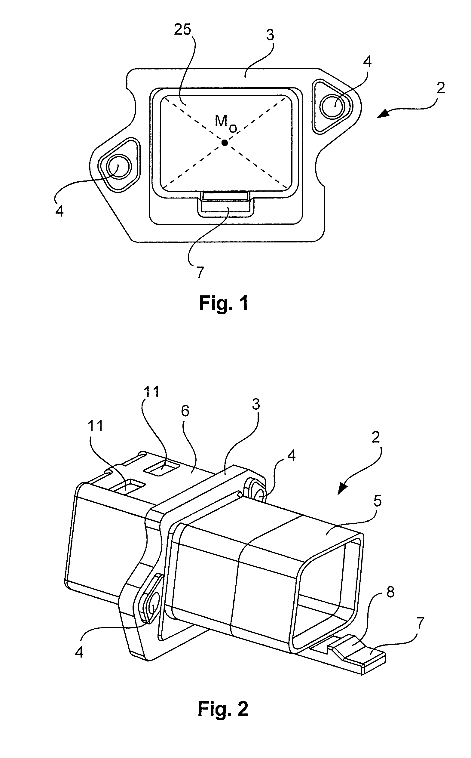
[0034]FIG. 1 shows a top view of a wall feedthrough,

[0035]FIG. 2 shows a perspective view of the wall feedthrough,

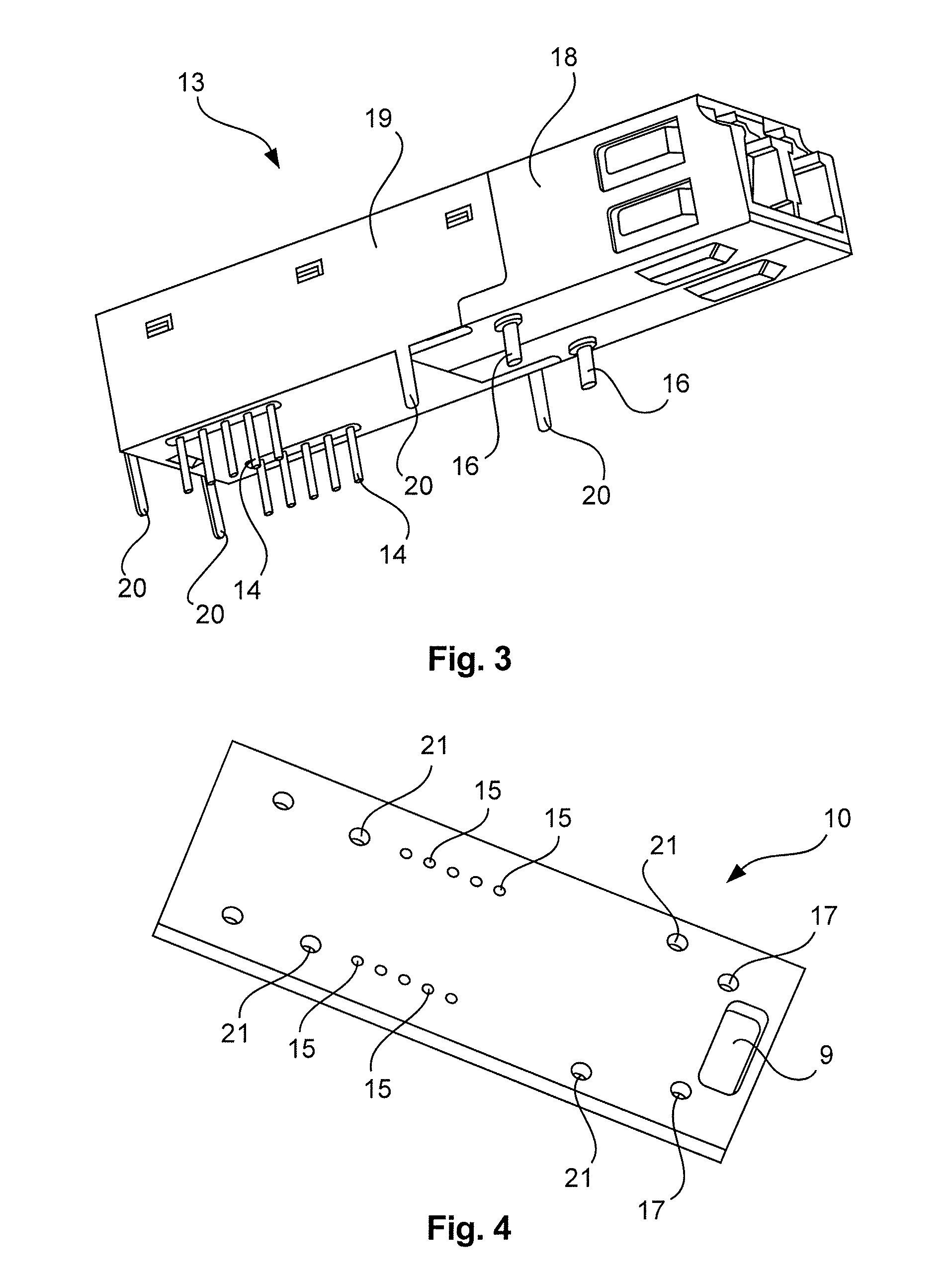
[0036]FIG. 3 shows a perspective view of an electronic component,

[0037]FIG. 4 shows a perspective view of a printed circuit board,

[0038]FIG. 5 shows a top view of a seal,

[0039]FIG. 5a shows a top view of an alternative seal,

[0040]FIG. 5b shows a further top view of an alternative seal,

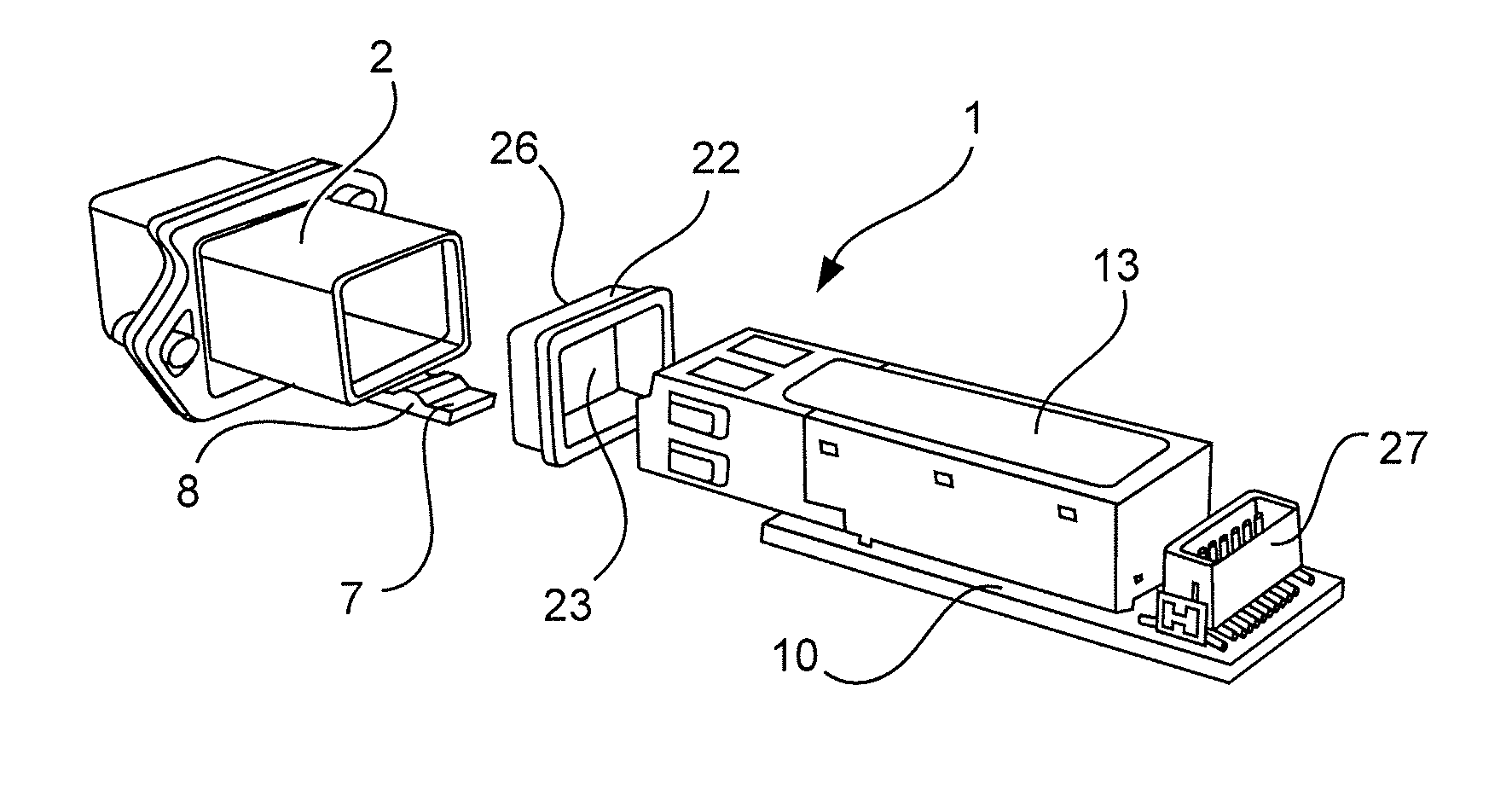
[0041]FIG. 6 shows a perspective, partially exploded view of a device socket, and

[0042]FIG. 7 shows a lateral view of the device socket with an inserted optical plug-in connector.

[0043]FIG. 1 shows a wall feedthrough 2 of a device socket 1 according to the invention. The wall feedthrough 2 is substantially designed as a cylinder with a square base area. Approximately at the centre, the cylinder has a circumferentially extending collar 3 that includes two bores 4 orientat...


PUM


Abstract

The invention relates to a device socket consisting of a wall feedthrough (2), a printed circuit board (10) and an electronic component (13) attached to the printed circuit board (10), wherein the device socket (1) comprises a locking means (7, 8), so that the printed circuit board (10) can be connected to the wall feedthrough (2), wherein the device socket (1) has at least one seal (22), which seal (22) comprises first means, by which the vertical position (y) of the electronic component (13) on the printed circuit board (10) is predetermined, wherein the seal (22) has an opening (23), into which the electronic component (13) can be inserted, wherein a centre (Md) is located in the opening plane of the seal (22) and the opening (25) of the wall feedthrough (2) has a centre (Mo), and wherein the centres (Md, Mo) have a distance from each other, the amount of which is greater than zero, wherein the printed circuit board (10) comprises second means, by which the horizontal position (x, z) of the electronic component (13) of the wall feedthrough (2) is predetermined, wherein the electronic component (13) comprises solder termination elements (14, 16, 20) and the second means of the printed circuit board are implemented as bores (15, 17, 21), into which the solder termination elements (14, 16, 20) of the electronic component (13) can be inserted.

Description

[0001]The invention relates to a device socket according to the preamble of claim 1.[0002]Such device sockets are used in electronic devices in order to supply these devices for example with data signals. However, the device socket can also be used to ensure the power supply of the devices.PRIOR ART[0003]DE 10 2009 011 388 B3 shows a plug-in connector that transmits optical signals via optical fibres which are held in so-called ferrules. The position of the ferrules in the plug-in connector is not standardised, so that the plug-in connectors must have at least some axial compensation for the ferrules in order to allow them to be designed so that they can be plugged into different sockets. Oftentimes, also horizontal compensation has to be provided in addition to the axial compensation. Such a plug-in connector is complex to manufacture and therefore expensive.[0004]If one wants to use low-cost optical plug-in connectors that have no length and height compensation (so-called conventi...

Claims


Application Information

Patent Timeline
Patent Type & Authority Applications(United States)
IPC IPC(8): G02B6/42G02B6/38
CPCG02B6/3825G02B6/3897G02B6/4292G02B6/428G02B6/4245G02B6/4261G02B6/4244
Inventor BUSSMANN, RAINERLINDKAMP, MARC
Owner HARTING ELECTRIC GMBH & CO KG
Why Eureka
Try Eureka