

Electricity-storage system, monitoring device, and power control system
- Summary
- Abstract
- Description
- Claims
- Application Information
AI Technical Summary
Benefits of technology
Problems solved by technology
Method used
Image

Examples
embodiment 1
Configuration
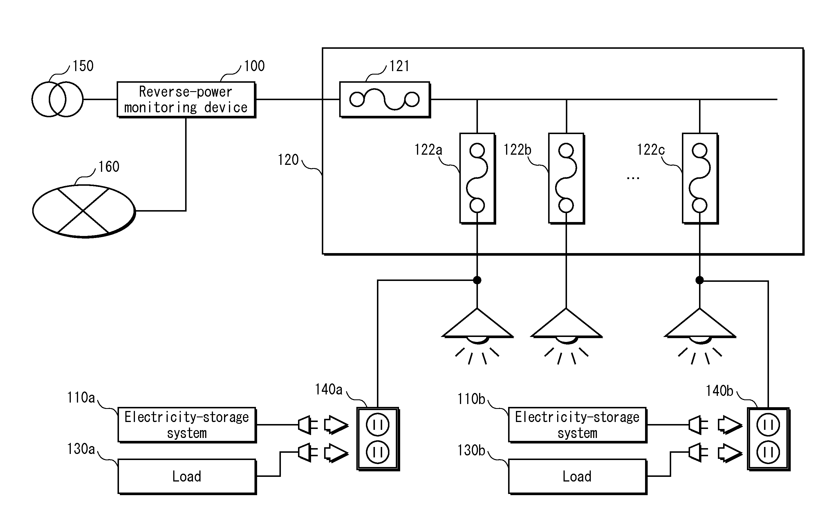
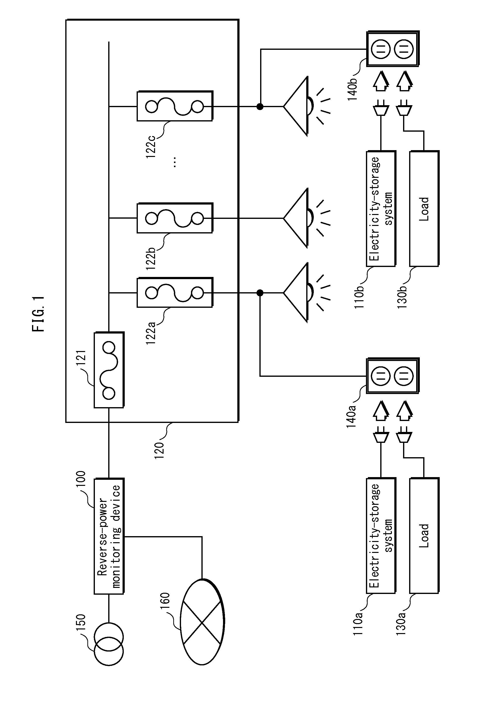
[0028]FIG. 1 is a system diagram showing configuration of a power control system. As shown in FIG. 1, the power control system includes a reverse-power monitoring device 100 and electricity-storage systems 110a, 110b connected to a power line network downstream of the reverse-power monitoring device 100. The reverse-power monitoring device 100 is connected to an electrical grid 150 upstream and to a distribution panel 120 downstream. Further, aside from the electrical grid 150 and the distribution panel 120, the reverse-power monitoring device 100 is also connected to a network 160. The distribution panel 120 is connected to the electricity-storage systems 110a, 110b and loads 130a, 130b via the power line network and electrical outlets 140a, 140b.
[0029]In the present embodiment, in order to simplify explanation, upstream of the reverse-power monitoring device 100 is referred to as the electrical grid and downstream of the reverse-power monitoring device 100 is referre...
embodiment 2
[0153]According to embodiment 1, above, the reverse-power monitoring device 100 detects power stoppage. According to embodiment 2, a case is described in which the electricity-storage systems, not the reverse-power monitoring device, detect power stoppage.
[0154]FIG. 11 is a function block diagram showing configuration of a reverse-power monitoring device 1100 pertaining to embodiment 2.
[0155]The reverse-power monitoring device 1100 includes a detector 1102 instead of the detector 202.
[0156]The detector 1102 has a function, unlike the detector 202 of embodiment 1, of only detecting power restoration and not detecting power stoppage. In a case in which power restoration is detected, the detector 1102 transmits an indication thereof to the controller 1104.
[0157]The controller 1104 has functions approximately the same as those of the controller 204 indicated in embodiment 1, with a point of difference below.
[0158]The controller 1104 is not notified of power stoppage from the detector 11...
PUM
 Abstract
Description
Claims
Application Information