A valve

a valve and valve body technology, applied in the field of valves, can solve the problems of increased chance of respiratory infections, weakened cough ability, spinal cord injury, etc., and achieve the effect of not affecting the switching speed

Active Publication Date: 2016-01-07
KONINKLJIJKE PHILIPS NV
View PDF6 Cites 7 Cited by
  • Summary
  • Abstract
  • Description
  • Claims
  • Application Information

AI Technical Summary

Benefits of technology

[0025]The seal portions may limit the movement of the valve element. In other words, the seal portions may be sized to prevent the valve members from moving past them.
[0040]Both the seal portions and valve members may be deformable. The combined deformation of the seal portions and the valve members can counteract larger deviations in the positions of the seal portions and the valve members.

Problems solved by technology

The presence of secretions, such as mucus, in the airways can trap dirt and bacteria and, if allowed to accumulate, can cause infection.
With many neuromuscular diseases, a loss of respiratory muscle strength results in a weakened ability to cough and an increased chance of respiratory infections.
This may also result from spinal cord injuries.
However, doing so typically increases friction within the valve and thus reduces the switching speed of the valve.

Method used


Image

  • A valve
  • A valve
  • A valve

Examples


first embodiment

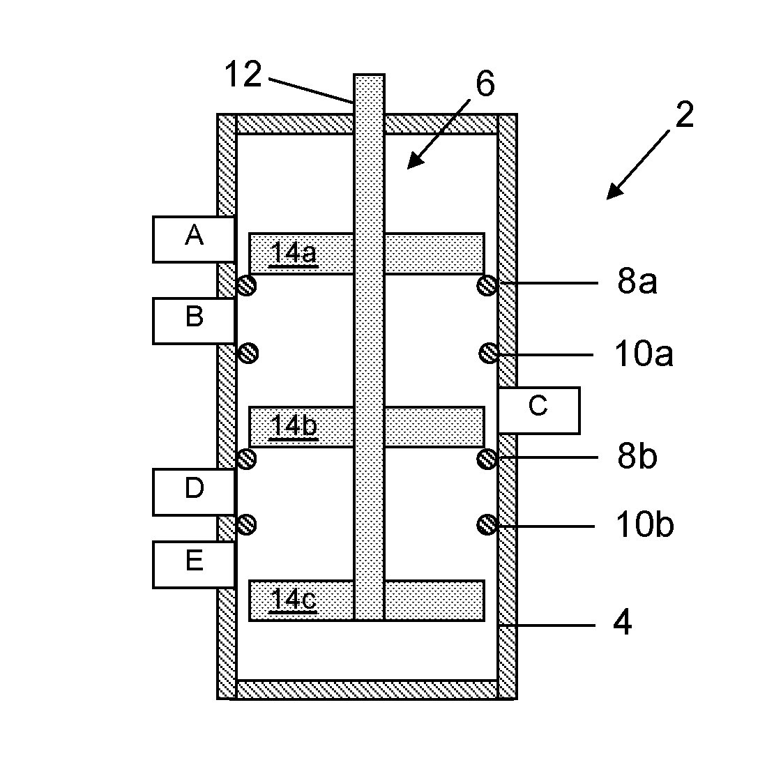
[0064]FIG. 1 shows a valve 2 according to the invention. The valve is a directional spool-type valve.

[0065]The valve 2 comprises a housing 4 in which a movable valve element 6 is disposed.

[0066]The housing 4 defines a generally cylindrical chamber. A plurality (five are shown in FIG. 1) of ports, labeled A-E, are provided in the wall of the housing 4. The ports A-E extend through the wall of the housing 4 and open into the chamber defined by the housing 4.

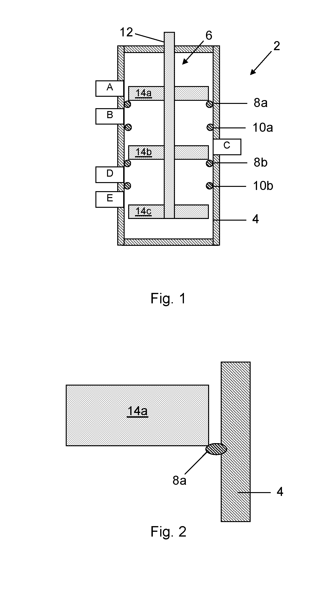
[0067]A plurality of seal portions are affixed to the housing 4 within the chamber. In the present embodiment, the seal portions are O-rings or other similar types of seals. The seal portions comprise an upper pair formed by a first upper seal portion 8a and a second upper seal portion 8b, and a lower pair formed by a first lower seal portion 10a and a second lower seal portion 10b.

[0068]The first and second upper seal portions 8a, 8b are spaced from one another, as are the first and second lower seal portions 10a, 10b. The spacin...

second embodiment

[0102]A valve 102 according to the invention will now be described with reference to FIG. 7.

[0103]The valve 102 has a similar construction to the valve 2. Consequently, the following description of the valve 102 will focus primarily on the differences between the first and second embodiments.

[0104]As per the valve 2 of the first embodiment, the valve 102 comprises a housing 104 in which a movable valve element 106 is disposed.

[0105]The housing 104 is identical to the housing 4 of the first embodiment and comprises ports A-E provided in the wall of the housing 104 and a plurality of seal portions affixed to the housing 104. As per the first embodiment, the seal portions comprise an upper pair formed by a first upper seal portion 108a and a second upper seal portion 108b, and a lower pair formed by a first lower seal portion 110a and a second lower seal portion 110b.

[0106]Like the valve element 6, the valve element 106 comprises a central stem 112 and a plurality of valve members 114...

third embodiment

[0123]A valve 202 according to the invention will now be described with reference to FIG. 8.

[0124]The valve 202 has a similar construction to the valve 2. Consequently, the following description of the valve 202 will focus primarily on the differences between the first and second embodiments.

[0125]As per the valve 2 of the first embodiment, the valve 202 comprises a housing 204 in which a movable valve element 206 is disposed.

[0126]The housing 204 is similar to the housing 4 of the first embodiment and comprises ports A-E provided in the wall of the housing 204 and a plurality of seal portions affixed to the housing 204. As per the first embodiment, the seal portions comprise an upper pair formed by a first upper seal portion 208a and a second upper seal portion 208b, and a lower pair formed by a first lower seal portion 210a and a second lower seal portion 210b. However, whilst the second upper seal portion 208b and the first lower seal portion 210a are each formed by an O-ring (or...


PUM


Abstract

There is provided a valve (2, 102, 302, 402) which comprises a housing (4, 04, 204, 304, 404) in which a movable valve element (6, 106, 206, 306, 406) having first and second valve members (14a, 14b; 114a, 114b; 214a, 214b; 314a, 314b; 414a, 414b) is disposed. A plurality of ports (A-E) are disposed in the housing, and first and second seal portions (8a, 8b; 10a, 10b; 108a, 108b; 110a, 110b; 208a, 208b; 210a, 210b; 308a, 308b; 310a, 310b; 408a, 408b; 410a, 410b) are connected to the housing. The first and second seal portions each have a sealed configuration in which first and second pairs of ports are sealed from one another with the first and second valve members respectively. At least one of the first seal portion and the first valve member is deformable such that, when only the first seal portion is in the sealed configuration with the first valve member, deformation allows the second seal portion to be brought into the sealed configuration with the second valve member, and / or at least one the second seal portion and the second valve member is deformable such that, when only the second seal portion is in the sealed configuration with the second valve member, deformation allows the first seal portion to be brought into the sealed configuration with the first valve member.

Description

FIELD OF THE INVENTION[0001]The invention relates to a valve and particularly, but not exclusively, to a valve for a cough assist device.BACKGROUND OF THE INVENTION[0002]The presence of secretions, such as mucus, in the airways can trap dirt and bacteria and, if allowed to accumulate, can cause infection. Coughing is the body's natural way of a removing mucus and other secretions from the lining of the airways, and thus reduces the risk of infection.[0003]A cough begins with a deep breath. The glottis (the opening at the top of the voice box) closes, allowing the pressure to build up in the lungs. The respiratory muscles contract, and the glottis opens, forcing air back out of the lungs.[0004]Muscles located in the rib cage, neck and abdomen play an important role during coughing. With many neuromuscular diseases, a loss of respiratory muscle strength results in a weakened ability to cough and an increased chance of respiratory infections. This may also result from spinal cord injur...

Claims


Application Information

Patent Timeline
Patent Type & Authority Applications(United States)
IPC IPC(8): A61M16/08A61M16/20F16K3/02F16K11/065F16K27/04
CPCA61M16/20A61M16/08F16K27/04F16K3/029F16K3/0227F16K11/0655A61M39/223F16K7/02F16K11/04F16K11/0525A61M2039/224A61M2039/2433A61M2205/0266A61M16/0009A61M16/204A61M16/205A61M2039/226A61M16/0006A61M16/202
Inventor VAN, DE, VEN, RICHARD, JOHANNUS, MARIA
Owner KONINKLJIJKE PHILIPS NV
Why Eureka
Try Eureka