Polymer ammunition cartridge having a metal injection molded primer insert

a technology of metal injection molding and polymer ammunition, which is applied in the field of polymer ammunition cartridges with metal injection molding primer inserts, can solve the problems of inability to provide satisfactory ammunition, high cost, and potentially hazardous, and achieve the characteristics of the cartridg

Inactive Publication Date: 2016-01-07
TRUE VELOCITY IP HLDG LLC
View PDF29 Cites 201 Cited by
  • Summary
  • Abstract
  • Description
  • Claims
  • Application Information

AI Technical Summary

Benefits of technology

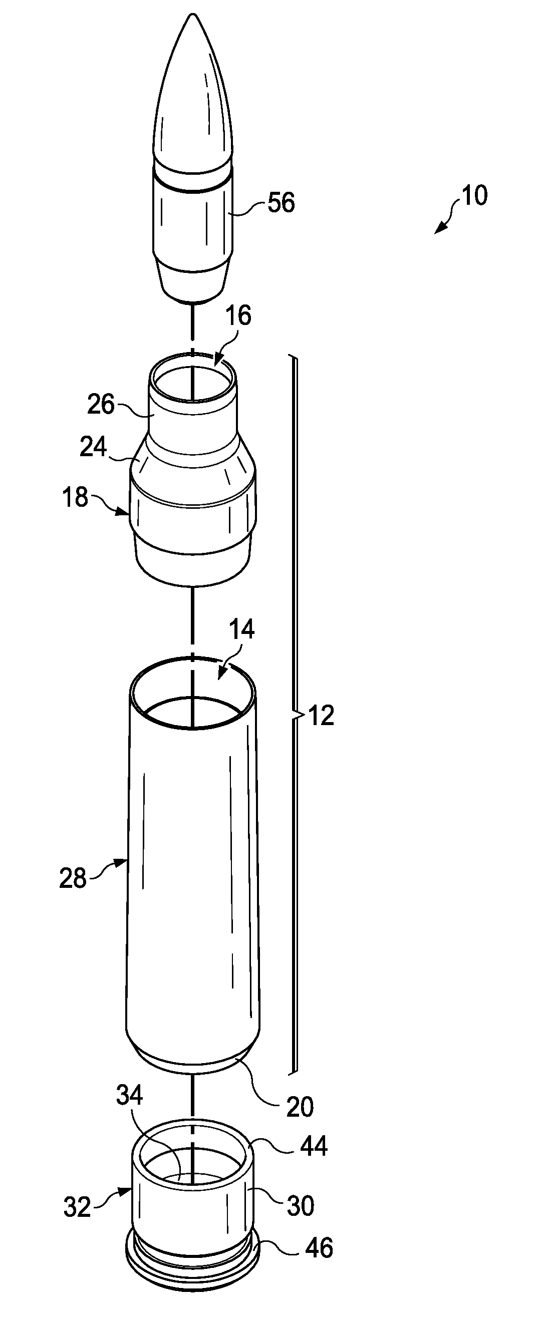
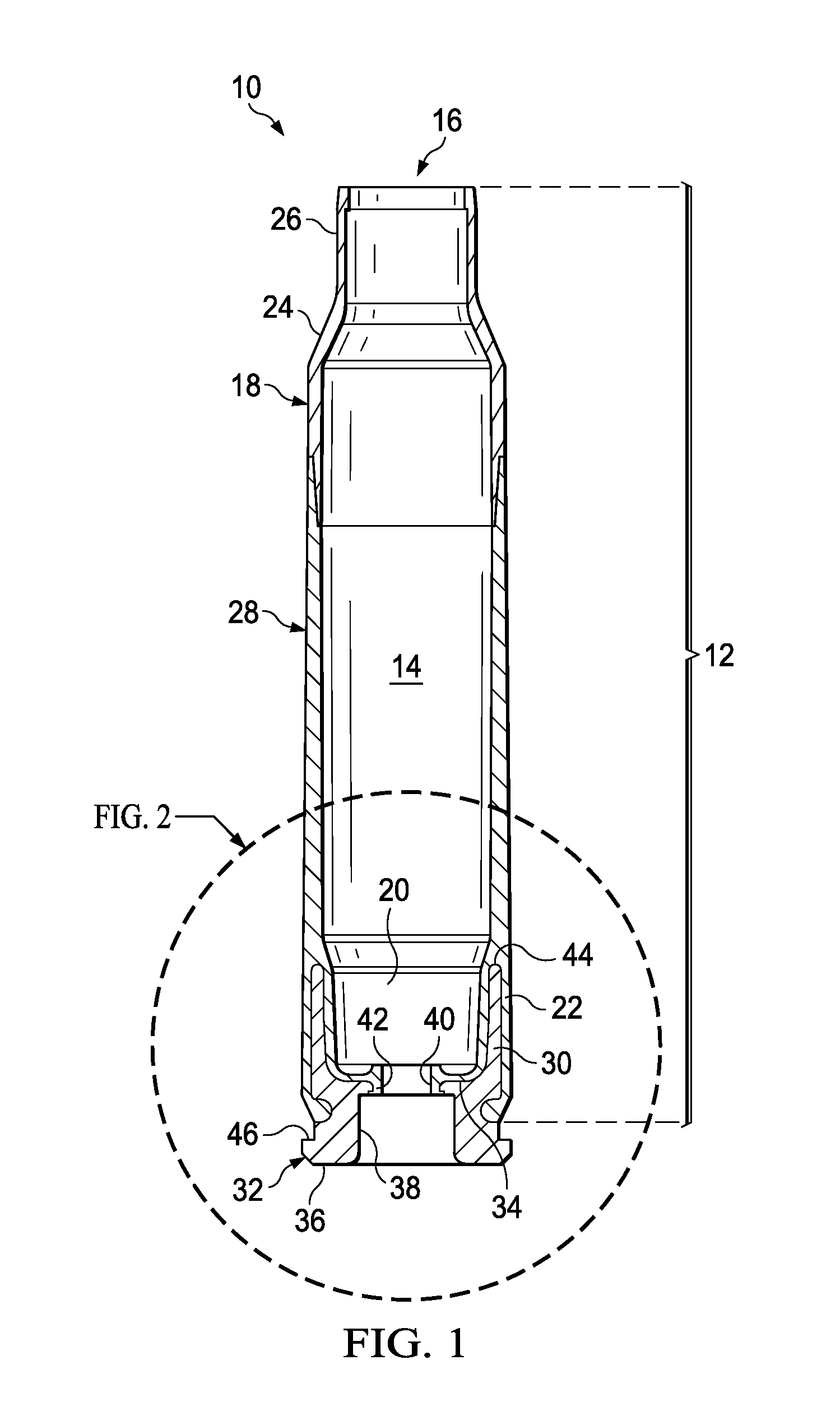
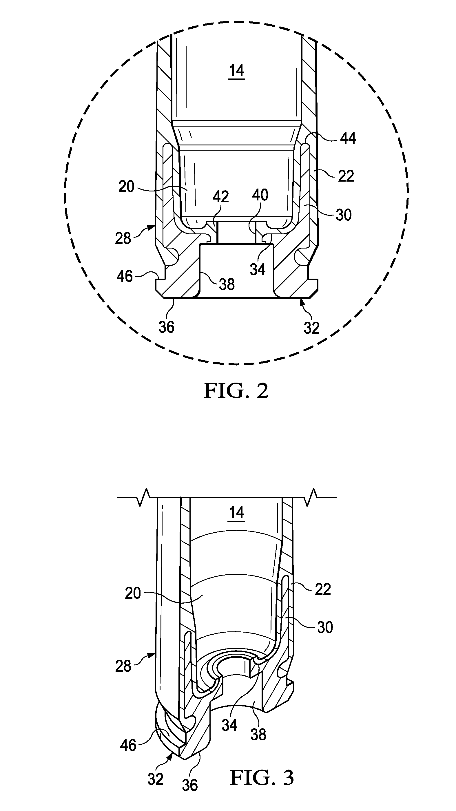
[0009]The present invention provides an ammunition cartridge having a molded primer insert comprising: an injection molded primer insert for polymer ammunition comprising a top surface opposite a bottom surface, a primer flash hole aperture positioned in the top surface extending through to the bottom surface, a substantially cylindrical coupling element extending away from the bottom surface forming an interior surface inside the substantially cylindrical coupling element and an exterior surface, a primer recess in the top surface that extends toward the bottom surface, a primer flash aperture positioned in the primer recess to extend through the bottom surface, and a flange that extends circumferentially about an outer edge of the top surface, wherein the flange is adapted to receive a polymer overmolding; a substantially cylindrical polymeric middle body extending from the substantially cylindrical primer insert to a cylindrical middle body coupling region molded from a first polymer, wherein the first polymer is molded over the flange, the inner circumferential surface and the outer surface and extends to the cylindrical middle body coupling region; a substantially cylindrical polymeric projectile end mated to the substantially cylindrical polymeric middle body, wherein the substantially cylindrical polymeric projectile end comprises a second polymer composition forming a projectile end coupling region that extends to a shoulder region that reduces to a neck region having a projectile aperture wherein the projectile end coupling region couples to the middle body coupling region; and a propellant chamber defined between the primer flash aperture and the projectile aperture.
[0010]The injection molded primer insert comprises a metal, an alloy, or a ceramic alloy. The injection molded primer insert comprises stainless steel or brass. The injection molded primer insert comprises 102, 174, 201, 202, 300, 302, 303, 304, 308, 309, 316, 316L, 316Ti, 321, 405, 408, 409, 410, 415, 416, 416R, 420, 430, 439, 440, 446 or 601-665 grade stainless steel. The ammunition cartridge further comprising a primer flash aperture groove positioned in the primer recess around the primer flash aperture and the first polymer composition extends into the primer flash aperture to form a flash hole. The first polymer composition is the same as the second polymer composition. The first polymer composition is a ductile polymer. The first polymer composition, the second polymer composition or both comprise a nylon polymer. The first polymer composition, the second polymer composition or both comprise a fiber-reinforced polymeric composite. The first polymer composition, the second polymer composition or both comprise between about 10 and about 70 wt % glass fiber fillers, mineral fillers, or mixtures thereof. The bullet aperture comprises one or more cannelures formed on an inner circumferential surface of the bullet aperture. The substantially cylindrical coupling region and the polymeric bullet-end coupling are welded or bonded together. The first polymer composition, the second polymer composition or both comprise polyurethane prepolymer, cellulose, fluoro-polymer, ethylene inter-polymer alloy elastomer, ethylene vinyl acetate, nylon, polyether imide, polyester elastomer, polyester sulfone, polyphenyl amide, polypropylene, polyvinylidene fluoride or thermoset polyurea elastomer, acrylics, homopolymers, acetates, copolymers, acrylonitrile-butadiene-styrene, thermoplastic fluoro polymers, inomers, polyamides, polyamide-imides, polyacrylates, polyetherketones, polyaryl-sulfones, polybenzimidazoles, polycarbonates, polybutylene, terephthalates, polyether imides, polyether sulfones, thermoplastic polyimides, thermoplastic polyurethanes, polyphenylene sulfides, polyethylene, polypropylene, polysulfones, polyvinylchlorides, styrene acrylonitriles, polystyrenes, polyphenylene, ether blends, styrene maleic anhydrides, polycarbonates, allyls, aminos, cyanates, epoxies, phenolics, unsaturated polyesters, bismaleimides, polyurethanes, silicones, vinylesters, urethane hybrids, polyphenylsulfones, copolymers of polyphenylsulfones with polyethersulfones or polysulfones, copolymers of poly-phenylsulfones with siloxanes, blends of polyphenylsulfones with polysiloxanes, poly(etherimide-siloxane) copolymers, blends of polyetherimides and polysiloxanes, and blends of polyetherimides and poly(etherimide-siloxane) copolymers. The injection molded primer insert is about 5 percent to about 30 percent smaller than a precured injection molded primer insert. The injection molded primer insert is about 10 percent to about 20 percent smaller than a precured injection molded primer insert. The injection molded primer insert is about 0.5, 1, 2, 3, 4, 5, 6, 7, 8, 9, 10, 11, 12, 13, 14, 15, 16, 17, 18, 19, 20, 21, 22, 23, 24, 25, 26, 27, 28, 29, or 30 percent smaller than a precured injection molded primer insert. The injection molded primer insert further comprises a flash hole groove that extends circumferentially about the primer flash aperture on the top surface in the primer recess. The bottom surface comprises a circumferential groove. The flange is a combination of a circumferential groove and one or more notches. The flange comprises one or more notches or scallops positioned circumferential. The flange comprises 1, 2, 3, 4, 5, 6, 7, 8, 9, 10, 11, 12, 13, 14, or 15 notches positioned circumferential. The flange comprises 1, 2, 3, 4, 5, 6, 7, 8, 9, 10, 11, 12, 13, 14, or 15 scallops positioned circumferential.

Problems solved by technology

Conventional ammunition cartridge casings for rifles and machine guns, as well as larger caliber weapons, are made from brass, which is heavy, expensive, and potentially hazardous.
Plastic cartridge casings have been known for many years but have failed to provide satisfactory ammunition that could be produced in commercial quantities with sufficient safety, ballistic, handling characteristics, and survive physical and natural conditions to which it will be exposed during the ammunition's intended life cycle; however, these characteristics have not been achieved.
Shortcomings of the known methods of producing plastic or substantially plastic ammunition include the possibility of the projectile being pushed into the cartridge casing, the bullet pull being too light such that the bullet can fall out, the bullet pull being too insufficient to create sufficient chamber pressure, the bullet pull not being uniform from round to round, and portions of the cartridge casing breaking off upon firing causing the weapon to jam or damage or danger when subsequent rounds are fired or when the casing portions themselves become projectiles.

Method used


Image

  • Polymer ammunition cartridge having a metal injection molded primer insert
  • Polymer ammunition cartridge having a metal injection molded primer insert
  • Polymer ammunition cartridge having a metal injection molded primer insert

Examples


Embodiment Construction

[0029]While the making and using of various embodiments of the present invention are discussed in detail below, it should be appreciated that the present invention provides many applicable inventive concepts that can be embodied in a wide variety of specific contexts. The specific embodiments discussed herein are merely illustrative of specific ways to make and use the invention and do not delimit the scope of the invention.

[0030]Reliable cartridge manufacture requires uniformity from one cartridge to the next in order to obtain consistent ballistic performance. Among other considerations, proper bullet seating and bullet-to-casing fit is required. In this manner, a desired pressure develops within the casing during firing prior to bullet and casing separation. Historically, bullets employ a cannelure, which is a slight annular depression formed in a surface of the bullet at a location determined to be the optimal seating depth for the bullet. In this manner, a visual inspection of ...


PUM

PropertyMeasurementUnit
thicknessaaaaaaaaaa
thicknessaaaaaaaaaa
thicknessaaaaaaaaaa

Abstract

One embodiment of the present invention provides a polymeric ammunition cartridge and methods of making and using the same. The cartridge includes a substantially cylindrical insert connected to a substantially cylindrical polymeric middle body. The substantially cylindrical insert includes a top surface opposite a bottom surface and a substantially cylindrical coupling element that extends from the bottom surface, a primer recess in the top surface that extends toward the bottom surface, a primer flash hole positioned in the primer recess to extend through the bottom surface, and a flange that extends circumferentially about an outer edge of the top surface. The substantially cylindrical polymeric middle body includes a substantially cylindrical polymeric bullet-end and a substantially cylindrical polymeric coupling end connected by a powder chamber, wherein the substantially cylindrical polymeric coupling end extends over the substantially cylindrical coupling element and covers a circumferential surface of the primer flash hole.

Description

CROSS-REFERENCE TO RELATED APPLICATIONS[0001]This application is a continuation of application Ser. No. 14 / 320,961, filed 1 Jul. 2014. The contents of which is incorporated by reference in its entirety.TECHNICAL FIELD OF THE INVENTION[0002]The present invention relates in general to the field of ammunition, specifically to compositions of matter and methods of making and using substantially cylindrical inserts made by metal injection molding.STATEMENT OF FEDERALLY FUNDED RESEARCH[0003]None.INCORPORATION-BY-REFERENCE OF MATERIALS FILED ON COMPACT DISC[0004]None.BACKGROUND OF THE INVENTION[0005]Without limiting the scope of the invention, its background is described in connection with lightweight polymer cartridge casing ammunition. Conventional ammunition cartridge casings for rifles and machine guns, as well as larger caliber weapons, are made from brass, which is heavy, expensive, and potentially hazardous. There exists a need for an affordable lighter weight replacement for brass ...

Claims


Application Information

Patent Timeline
Patent Type & Authority Applications(United States)
IPC IPC(8): F42B5/307
CPCF42B5/307F42C19/083B22F3/225B22F5/06C22C33/0257B22F2998/10B22F3/004F42B5/30C22C14/00C22C33/0285C22C38/02C22C38/04C22C38/18C22C38/42C22C38/44C22C38/48C22C38/58F42C19/0807B22F9/04B22F1/108B22F3/1025B22F3/1021F42B5/313F42B33/04F42C19/0823F42B5/025F42B5/02C04B35/64C22C1/0458F42B33/001F42B33/02B22F3/10B22F5/00F42B33/00
Inventor BURROW, LONNIE
Owner TRUE VELOCITY IP HLDG LLC
Why Eureka
Try Eureka