Magazine retention device

a retention device and magazine technology, applied in the field of ammunition storage devices, can solve the problems of insecure and vulnerable ammunition magazines, obstructing the user's quick and efficient grasping of magazines by the latch mechanism, and affecting the safety of ammunition magazines, so as to achieve constant friction force

Active Publication Date: 2016-01-07
HEAVEN SENT GAMING
View PDF7 Cites 25 Cited by
  • Summary
  • Abstract
  • Description
  • Claims
  • Application Information

AI Technical Summary

Benefits of technology

[0019]In all embodiments of the inventive device, the inventive essence that improves upon the known prior art is the differential in height between a first pair of opposing side panels of a first height and a second pair of opposing side panels of a second, greater height coupled with biasing means whereby at least one pair of opposing side panels are biased inwardly toward one another. The result is a pocket applying constant frictional force to the sides of an inserted magazine, but which allows the magazine to be rotated out of the pocket once withdrawn far enough that a round of ammunition may clear the shorter pair of opposing side panels and the magazine may be laterally rotated out of the pocket while the taller pair of opposing side panels continue to apply frictional force against the rigid sides of the ammunition magazine. Hence, a round of ammunition exposed at the base of an ammunition magazine is released from the pocket without being caught or hung on an inwardly biased side of the pocket, a substantial problem in the known prior art. Further, the continued use of inward biasing of at least one pocket panel continues to allow constant pressure of frictional force against the rigid exterior of the magazine, thus allowing the secure retention and stowing of the magazine despite jarring or other forces acting on the magazine to cause it to eject or be inadvertently released from the top opening of the pocket.
[0020]It is a primary objective of the herein disclosed invention to provide for the secure storage and retention of at least one ammunition magazine without causing a loss or waste of ammunition rounds upon removal of the magazine and transfer of the same to a weapon.
[0021]It is a further primary objective of the now disclosed invention to provide a device capable of securely stowing a variety of items that a user may carry and require to be conveniently accessible, including, without limitation, a rifle magazine, a pistol or handgun, a flashlight, a cellular telephone, a medication dispenser or storage bottle, a notepad, a keyring, a remote control, a stun gun or taser device, a folding knife, a pepper spray canister, or the like.
[0022]It is a further objective of the now disclosed invention to provide a device capable of securely stowing a variety of items that itself is extraordinarily durable for use under heavy use and / or extreme conditions.
[0024]It is a still further objective of the now disclosed invention to provide a retention device comprising a pouch, pocket or well defined by two pairs of opposing side panels and a bottom panel, wherein one of the pairs of opposing side panels is rigid and greater in length than the other pair of opposing side panels, the upper ends of the taller pair of side panels serving as guides for the easy insertion and extraction of items from the device.

Problems solved by technology

Namely, the flap mechanism prevalent in the prior art effectively restrains an ammunition magazine from falling out of the pouch through the upward-oriented opening, however, the flap mechanism also obstructs a user from quickly and efficiently grasping the magazine when needed to transfer the magazine from the pouch to an otherwise unloaded weapon.
In combat circumstances the delay occasioned by the two additional motions necessary to negotiate the flap mechanism can be the difference between life and death for a user.
While the above-referenced devices featuring a pouch without a flap mechanism known in the prior art dispense with unnecessary motions in negotiating the flap mechanism and thereby improve the speed and efficiency whereby a user might grasp, transfer and load an ammunition magazine into an unloaded weapon, the omission of the securing flap leaves the ammunition magazine insecure and vulnerable to jarring or forces that might inadvertently cause the ejectment or loss of the magazine through the top opening of the pouch.
Further, the tailoring of the pouch in these devices to ensure a tight fit for a specific magazine begets a lack of universality in ability to securely retain and store ammunition magazines of varying shapes and sizes.
While the identified precursor prior art represents a significant improvement over the other prior art known, the precursor prior art has its own shortcoming in that the design tends to cause loss of ammunition from the magazine during transfer of the magazine from the precursor pocket to the unloaded weapon.
As with the introduction of two additional motions necessary to negotiate the flap mechanism in the other known prior art, the loss or waste of ammunition caused by the clamping of the precursor prior art device upon an exposed round will cause a user to either (i) waste time recovering and reinserting the dislodged round into the magazine, or (ii) run out of ammunition sooner, each result possibly causing the unnecessary wounding or death of the user in a combat circumstance.

Method used


Image

  • Magazine retention device
  • Magazine retention device
  • Magazine retention device

Examples


Embodiment Construction

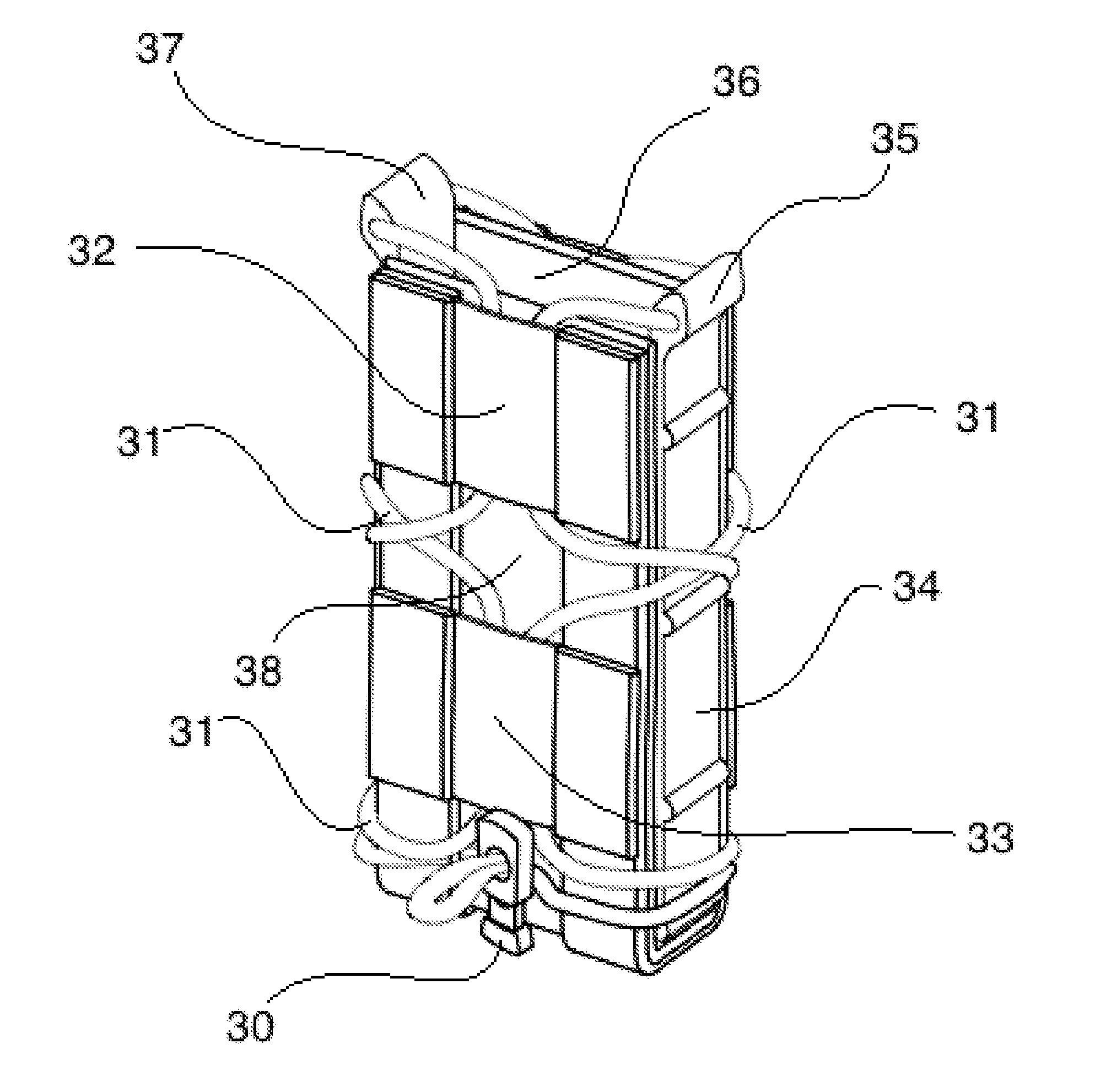
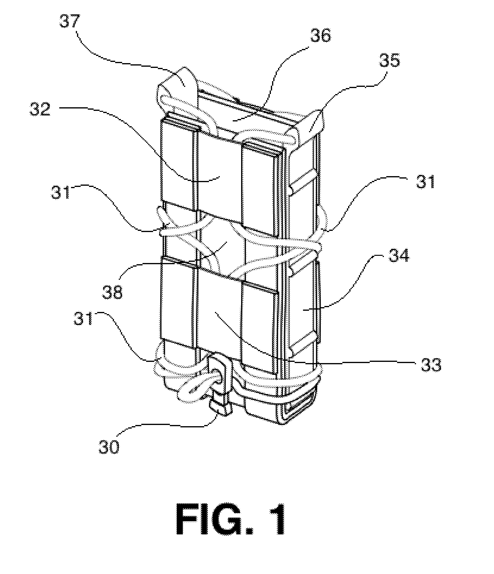
[0032]Referring now to the invention in more detail, in FIG. 1 and FIG. 3 there is shown a first preferred embodiment of the first disclosed invention, FIG. 1 depicting the embodiment and FIG. 3 depicting the component parts of the embodiment to facilitate a more full understanding of the embodiment. Referring now to FIG. 1 and FIG. 3 there is shown a magazine retention device comprising a pocket formed of a single length of pliable material serving as both a front side panel 38 and back side panel 36 and a U-shaped molded structural component riveted to the length of pliable material through a first bottom channel perforation 50 and a second bottom channel perforation 51, thus forming a bottom panel 61, a right side panel 34, and an opposing left side panel 55. Further shown is a distended elastic bungee 31 wrapped about the exterior of the pocket formed by the front side panel 38, back side panel 36, bottom panel 61, right side panel 34, and left side panel 55, the distended elast...


PUM


Abstract

An apparatus for the secure stowing of a magazine, the apparatus comprising a pocket defined by a first pair of opposing side panels and a second pair of opposing side panels, the first pair of opposing side panels being in substantially perpendicular plane to the second pair of opposing side panels and the first pair of opposing side panels being shorter in height than the second pair of opposing side panels, a bottom panel, and a top opening; biasing means whereby at least one pair of opposing side panels are biased toward one another; and means of attachment whereby the pocket may be attached to a person or object.

Description

CROSS-REFERENCE TO RELATED APPLICATIONS[0001]This application claims the benefit of priority to U.S. Provisional Application No. 61 / 770,308 filed Feb. 27, 2013. This application further claims the benefit of priority to PCT Application Number PCT / US14 / 19169 filed on Feb. 27, 2014 and claiming priority to U.S. Provisional Application No. 61 / 770,308 filed Feb. 27, 2013. The content of both U.S. Provisional Application No. 61 / 770,308 and PCT Application Number PCT / US14 / 19169 filed on Feb. 27, 2014 are incorporated by reference herein in their entirety.STATEMENT REGARDING FEDERALLY SPONSORED RESEARCH OR DEVELOPMENT[0002]Not Applicable.THE NAMES OF THE PARTIES TO A JOINT RESEARCH AGREEMENT[0003]Not Applicable.INCORPORATION-BY-REFERENCE OF MATERIAL SUBMITTED ON A COMPACT DISC[0004]Not Applicable.BACKGROUND OF THE INVENTION[0005](a) Field of the Invention[0006]The present invention is in the technical field of devices designed for the holding of ammunition. More particularly, the present i...

Claims


Application Information

Patent Timeline
Patent Type & Authority Applications(United States)
IPC IPC(8): F42B39/02B65D25/04B65D25/20B65D63/10
CPCF42B39/02B65D25/20B65D63/10B65D25/04
Inventor GADAMS, MATTHEWHIGDON, ALBERTHIGDON, REBECCA
Owner HEAVEN SENT GAMING
Why Eureka
Try Eureka