Constant tension paying-off brake device and using method thereof

A braking device, constant tension technology, used in transportation and packaging, insulation of conductors/cables, electrical components, etc., can solve problems such as high energy consumption, high maintenance costs, and increase waste wire rate, and achieve low accuracy requirements, The effect of improving process level and product quality

Pending Publication Date: 2020-01-10
BAODING TIANWEI WIRE MFG
View PDF0 Cites 1 Cited by
  • Summary
  • Abstract
  • Description
  • Claims
  • Application Information

AI Technical Summary

Problems solved by technology

Because the bare wire is in a soft state when it is painted, it is easy to shrink when the tension is high. When the bare wire wound on the bobbin is drawn into the annealing, painting and other process equipment by the traction take-up machine, if the pay-off is not stable, Suspension of tension can easily lead to shrinkage and vibration of bare wires, especially when producing high-yield strength enameled wires, the size changes even more, and even wire breakage
Due to the unstable tension of the pay-off line, the thickness of the paint will be uneven, which cannot meet the process requirements.
Therefore, the unstable pay-off tension will greatly increase the waste wire rate and seriously affect the product quality.
At present, in the field of constant tension pay-off in China, the pneumatic brake pay-off device requires an air compressor to continuously and stably provide air source, which consumes a lot of energy, while the brake brake pay-off device has very high technical requirements for the bobbin and needs to be dynamically balanced. Huge purchase and maintenance costs

Method used


Image

  • Constant tension paying-off brake device and using method thereof
  • Constant tension paying-off brake device and using method thereof
  • Constant tension paying-off brake device and using method thereof

Examples


Embodiment Construction

[0018] The technical solutions of the present invention will be further described in detail below in conjunction with the accompanying drawings and embodiments.

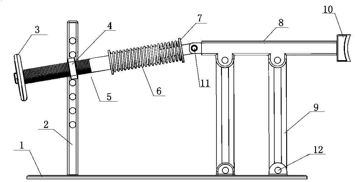
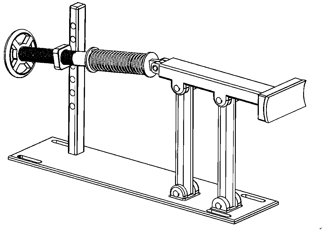
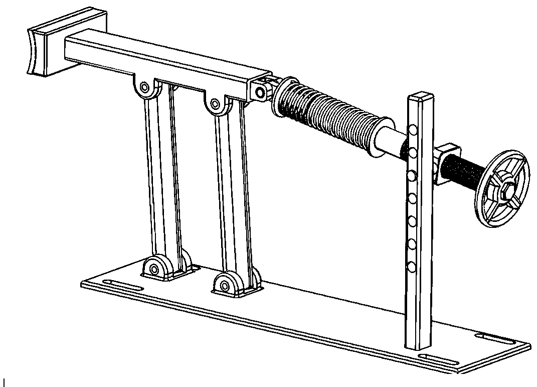
[0019] A constant tension release brake device, comprising a base 1, a height-adjustable support column 2, a twistable nut 4, a brake lever 8, a parallel double link 9, a brake pad 10 and a tension adjustment mechanism, the height-adjustable support column 2 is arranged on the base 1, and the height-adjustable support column 2 is provided with more than one position hole, and the twistable nut 4 is arranged in the position hole of the height-adjustable support column 2; the tension adjustment mechanism includes an adjustment screw rod 5, a spring 6 and a slide Rod 7, one end of adjusting screw rod 5 is connected with twistable nut 4 by thread, and the other end of adjusting screw rod 5 is open, and the inside is provided with the slideway that communicates with opening, slide bar 7 one end is slidably arranged in the ...


PUM


Abstract

The invention relates to a constant tension paying-off brake device and a using method thereof, and belongs to the technical field of production of enamel-cover winding wires for large-sized power transformers. According to the technical scheme, a height-adjustable supporting column (2) is provided with one or more placement holes, and a twistable nut (4) is arranged in the position holes of the height-adjustable supporting column (2); one end of an adjusting screw (5) is connected with the twistable nut (4) through a thread, the other end of the adjusting screw (5) is opened, the adjusting screw (5) is internally provided with a slide way communicated with the opening, one end of a slide rod (7) is slidably arranged in the slide way, the other end of the slide rod is hinged to a brake rod(8), and a spring (6) sleeves the adjusting screw and the slide rod; a brake sheet (10) is arranged at the top of the brake rod, the tops of two connecting rods are hinged to the brake rod, and the bottom of the two connecting rods are hinged to a base (1). According to the constant tension paying-off brake device, there is no need to provide compressed air for an air compressor, meanwhile, the requirement for the precision of a paying-off bobbin tool is not high, and a large amount of expenditure is reduced.

Description

technical field [0001] The invention relates to a constant tension wire releasing brake device and a using method thereof, and belongs to the technical field of production of enamelled winding wires for large-scale power transformers. Background technique [0002] Enameled wires for transformer windings are generally made by annealing copper or aluminum conductors of a certain specification, then coating insulating varnish, and then drying and heating to make the insulating varnish cross-linked and cured. At present, the manufacturing process of enameled wire is relatively mature. Most of the bare wires used in the manufacture of enameled wires are made by extrusion or wire drawing. The painting process requires that the bare wires should be soft wires, and the bare wires of the extrusion process themselves are soft wires. The drawing bare wire must be annealed before painting to turn the hard wire into a soft wire. Because the bare wire is in a soft state when painted, it ...

Claims


Application Information

Patent Timeline
Patent Type & Authority Applications(China)
IPC IPC(8): B65H49/20B65H59/06B65H59/36H01B13/06
CPCB65H49/20B65H59/06B65H59/36B65H2701/34H01B13/065
Inventor 曹士亮崔金宝
Owner BAODING TIANWEI WIRE MFG
Why Eureka
Try Eureka