Wireless detonation system, wireless detonation method, and detonator and explosive unit used in same

Active Publication Date: 2016-01-07
NOF CORP
View PDF5 Cites 10 Cited by
  • Summary
  • Abstract
  • Description
  • Claims
  • Application Information

AI Technical Summary

Benefits of technology

[0032]Due to this configuration, since the operation frequency of a signal transmitted from the blasting controller to the wireless initiating detonator is set to be greater than or equal to 100 kHz, and to be less than or equal to 500 kHz, and the soft magnetic coil antenna is used as the detonator antenna, it is possible to realize the wireless initiation method by which it is possible to further reduce an amount of time required to perform work in the vicinity of the blasting face, that is, an amount of time for adjusting the directivity of the detonator antenna, for the charging step, and for the blasting controller antenna extending step.
[0033]In the wireless initiation method according to the above aspect, when the display device is attached to the wireless initiating detonator via the cable with a leng

Problems solved by technology

An extending operation for extending the loop antenna disposed close to the entire circumference of the tunnel side wall while the loop antenna being wound in 30 turns, requires a considerable amount of labor effo

Method used


Image

  • Wireless detonation system, wireless detonation method, and detonator and explosive unit used in same
  • Wireless detonation system, wireless detonation method, and detonator and explosive unit used in same
  • Wireless detonation system, wireless detonation method, and detonator and explosive unit used in same

Examples


Embodiment Construction

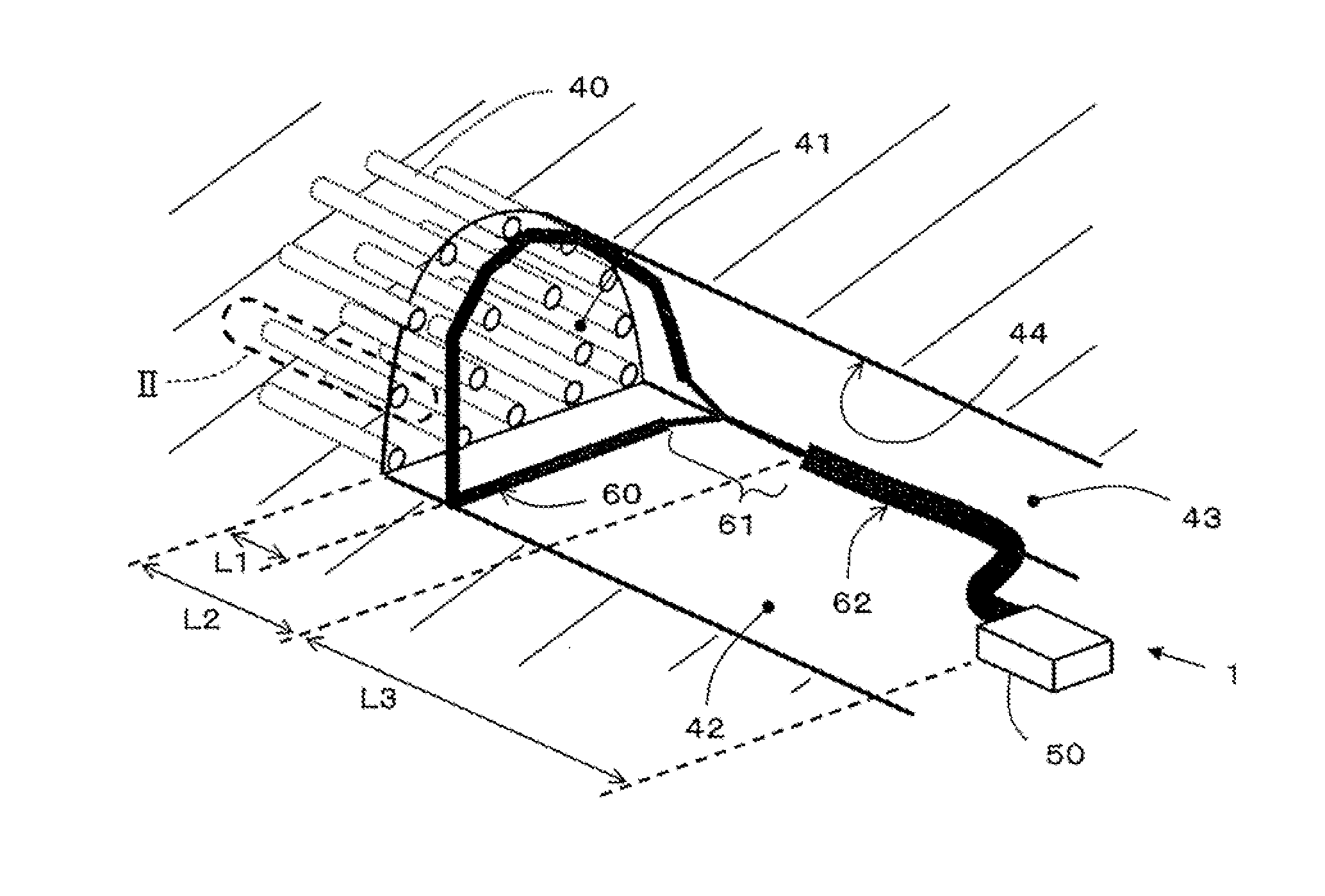
[0044]Hereinafter, various examples of the present invention, used at a tunnel excavation site, will be described with reference to the accompanying drawings.

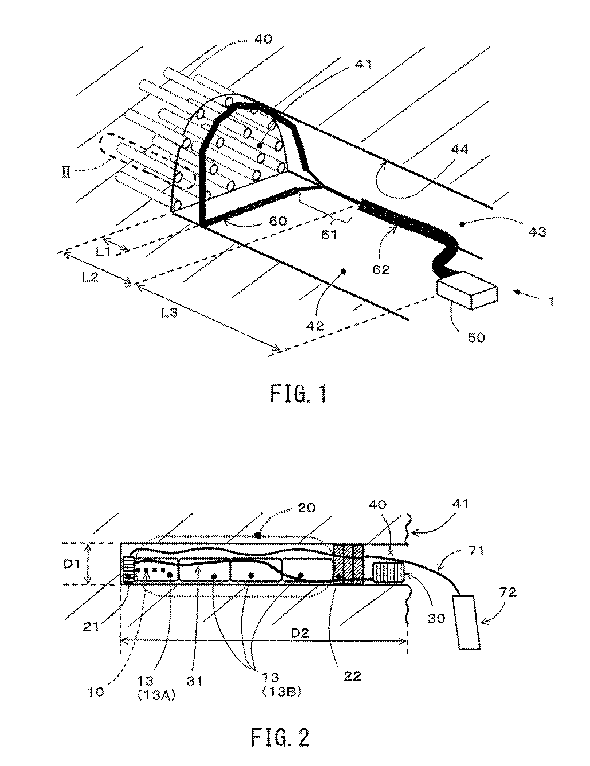
Entire Configuration (FIG. 1) of Wireless Initiation System and State (FIG. 2) of Charging of Explosive Unit Into Blast Hole

[0045]A wireless initiation system 1 is formed of an explosive unit 20 charged into a blast hole 40 that is drilled into a blasting face 41; a blasting controller 50 that is disposed at a remote position away from the blast hole 40, and can wirelessly transmit and receive signals to and from the explosive unit 20; a blasting controller antenna 60 that extends in the vicinity of the blasting face 41.

[0046]For example, the blast hole 40 is a hole drilled with a diameter D1 of approximately 5 cm and a depth D2 of approximately 2 m, and the blast hole 40 is not limited to a specific size.

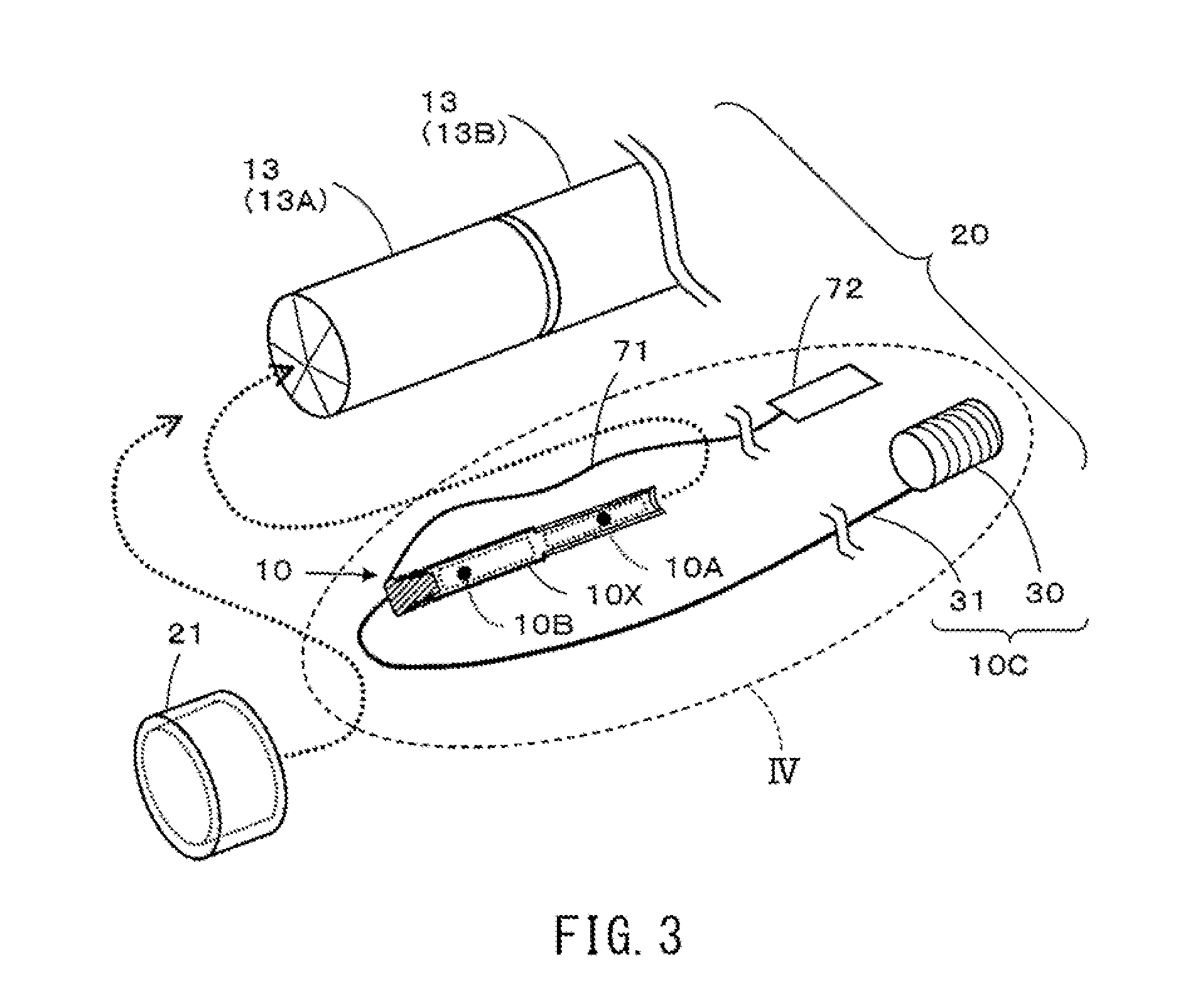
[0047]As illustrated in FIGS. 3 and 4, a wireless initiating detonator 10 is formed of an initiator 10A; a controller 10B; a...


PUM


Abstract

A wireless detonator is provided with: a detonation part; a control part for the detonation part, the control part being connected to the detonation part; a tube for accommodating the detonation part and the control part; and a detonation-side antenna used by the control part for wireless communication and capable of being used for sending and receiving without separately having a transmission-only antenna and a reception-only antenna; the detonation-side antenna being a soft magnetic body coil antenna, and the control part receiving, via the detonation-side antenna, a transmission signal at an operating frequency of 100-500 KHz.

Description

RELATED APPLICATIONS[0001]The present application is a National Phase entry of PCT Application No. PCT / JP2013 / 084923, filed Dec. 26, 2013, which claims priority from JP Patent Application No. 2013-000909, filed Jan. 8, 2013, said applications being hereby incorporated by reference herein in their entirety.BACKGROUND OF THE INVENTION[0002]The present invention relates to a wireless initiation system, a wireless initiation method, and a detonator and an explosive unit used therein for tunneling.[0003]In the related art, there is a blasting method used for drilling a plurality of blast holes with a diameter of approximately several centimeters and a depth of approximately several meters in a blasting face (which is a tunnel working face) in a boring direction, charging explosives into the blast holes, the blasting of the explosives being able to be wirelessly initiated, wirelessly transmitting an initiation signal from a remote position apart from the blasting face, and exploding the b...

Claims


Application Information

Patent Timeline
IPC IPC(8): F42C13/04F42D1/045
CPCF42D1/045F42C13/04
Inventor HIKONE, SATOSHITASAKI, YOJI
Owner NOF CORP
Why Eureka
Try Eureka