Carton and stress relieving pattern for handle

Inactive Publication Date: 2016-01-14
C W ZUMBIEL
View PDF23 Cites 32 Cited by
  • Summary
  • Abstract
  • Description
  • Claims
  • Application Information

AI Technical Summary

Benefits of technology

[0011]These and other drawbacks in the prior art have been addressed and overcome with a blank, carton, package and handle configuration of this invention. A carton of this i

Problems solved by technology

Naturally, thicker, denser and stronger paperboard stock is typically more expensive and carton manufacturers who produce great quantities of paperboard cartons are interested in providing the most economical carton without sacrificing functionality, including carton strength.
Paperboard stock that is thinner and made from non-virgin pulp is often less expensive than thicker stock made from virgin pulp, but the strength characteristics of such pa

Method used


Image

  • Carton and stress relieving pattern for handle
  • Carton and stress relieving pattern for handle
  • Carton and stress relieving pattern for handle

Examples


first embodiment

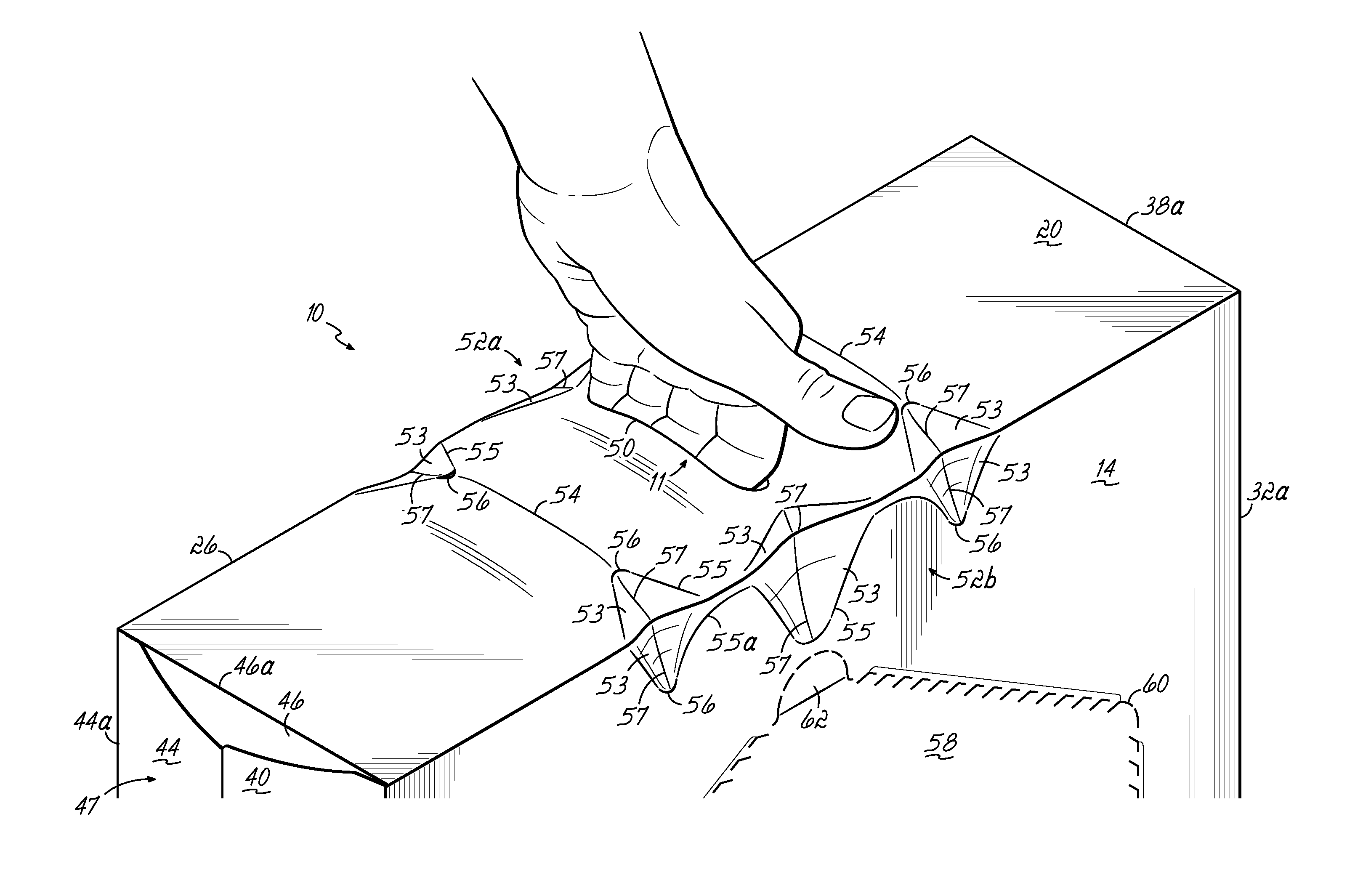
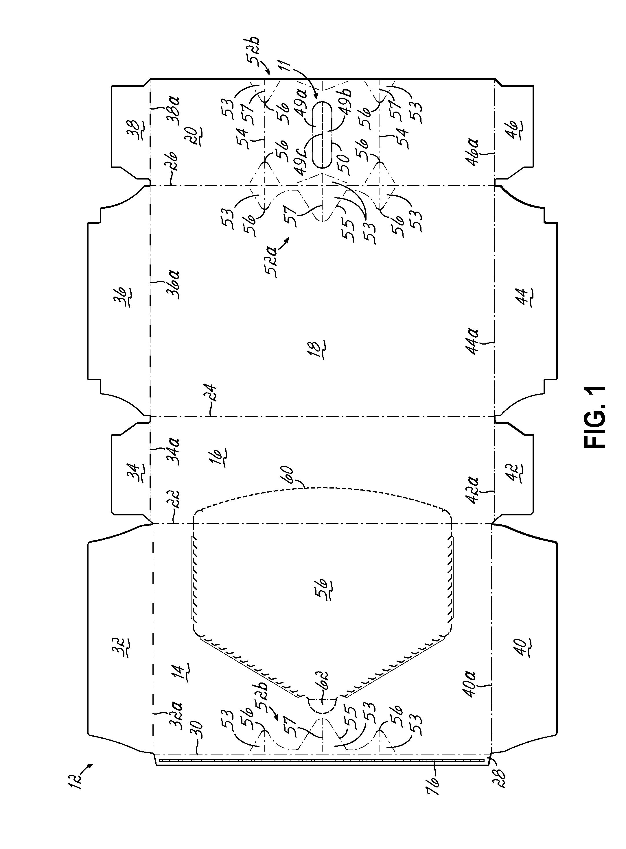
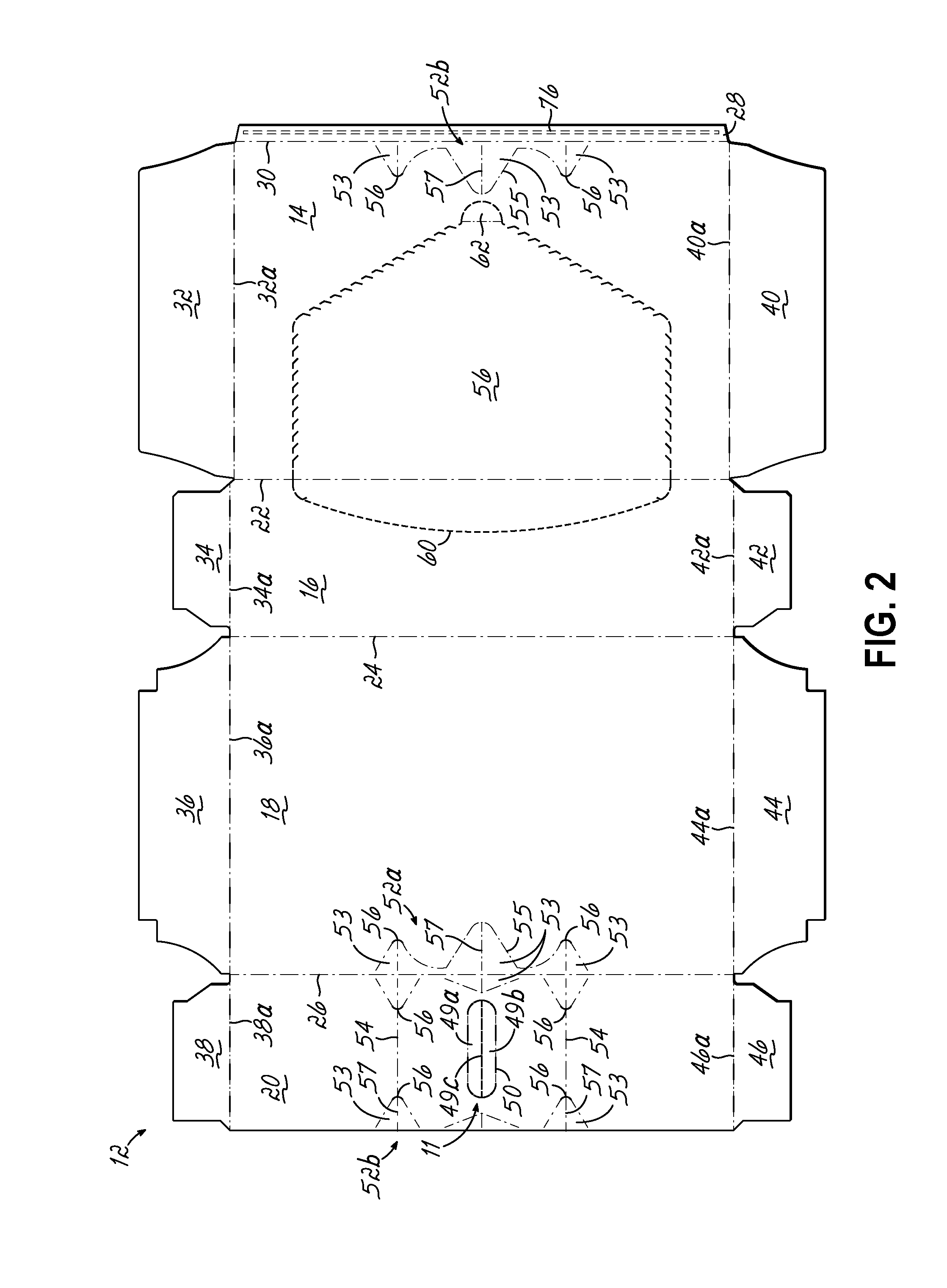
[0031]FIGS. 3 to 7 illustrate a carton 10 having a carrying handle 11 in accordance with one of the embodiments of this invention. FIGS. 1-2 illustrate a blank 12 from which the carton 10 of FIGS. 3-7 is formed. An alternative carton blank 12 is shown in FIGS. 8-9. Containers “C” arranged in a 4×6 array are shown in FIGS. 4A, 4B, 5A and 5B as an aid in understanding the invention. However, the various embodiments of this invention are applicable to other types of containers (glass bottles, PET bottles, etc.) as well as other container arrangements (3×4, 2×6, 2×2, etc.) including various orientations of the containers in the carton 10. More specifically in the embodiment shown in FIGS. 3-7, the containers C are arranged in a matrix consisting of four vertically disposed tiers each including six 12 ounce cans. The containers C in each tier are disposed on their sides in a side-by-side parallel fashion. Each container C includes a rim 13 on a longitudinal end of the can as shown within...

second embodiment

[0040]As shown in the blank 12 of a second embodiment as shown in FIGS. 8-9, a primary reinforcing panel 64 is joined to the glue flap 28 adjacent the side panel 14. A secondary reinforcing panel 66 is joined to a longitudinal end of a primary reinforcing panel 64 along a secondary reinforcing panel fold line 68. A cut line 70 is formed between the adjacent edges of the secondary reinforcing panel 66 and the glue flap 28 to permit the secondary reinforcing panel 66 to be pivoted about the secondary reinforcing panel fold line 68 onto the primary reinforcing panel 64. Handle apertures 72a, 72b are provided in each of the primary and secondary reinforcing panels 64, 66, respectively, and are mirror images of one another about the secondary reinforcing panel fold line 68 so that when the reinforcing panels 64, 66 are in face-to-face juxtaposition, the respective apertures 72a, 72b are in alignment and registration.

[0041]Additionally, in the primary reinforcing panel 64, a second patter...


PUM

PropertyMeasurementUnit
Thicknessaaaaaaaaaa
Stress optical coefficientaaaaaaaaaa

Abstract

A carton blank is assembled into a carton for beverage containers, the blank having a number of panels including a top panel, a bottom panel and a pair of side panels each joined by a fold line to an adjacent one of the panels. A number of end flaps are each joined by an end flap fold line to one of the panels and the end flaps are adapted to be folded upon selected other end flaps to form composite end panels of the carton. A carrying handle is formed in a selected one of the panels and adapted to be grasped by a user to carry the erected carton filled with the beverage containers. A pattern of stress-relieving lines are formed in the carton blank to produce a desired buckling of the carton when erected, filled and lifted to avoid tearing of the carton material.

Description

CROSS REFERENCE TO RELATED APPLICATIONS[0001]This application is a continuation-in-part of U.S. patent application Ser. No. 13 / 678,892, filed on Nov. 16, 2012, which claimed priority to U.S. Provisional Patent Application Ser. No. 61 / 560,832, filed Nov. 17, 2011 and U.S. patent application Ser. No. 13 / 053,384, filed Mar. 22, 2011, which in turned claimed priority to U.S. Provisional Patent Application Ser. No. 61 / 318,015, filed Mar. 26, 2010 and U.S. Provisional Patent Application Ser. No. 61 / 346,602, filed May 20, 2010. Each of these prior applications is hereby incorporated by reference in its entirety.BACKGROUND OF THE INVENTION[0002]This invention relates to cartons, and more particularly, to a beverage container carton having a carrying handle.[0003]In the marketing of soft drinks, beer and other beverages, it is well known to sell those retail consumer products in containers, such as cans, glass bottles, PET bottles or other containers which are grouped together in packs of fo...

Claims


Application Information

Patent Timeline
IPC IPC(8): B65D5/54B65D5/02B65D5/468B65D71/36
CPCB65D5/542B65D5/0227B65D5/4608B65D71/36B65D2571/0066B65D2571/00728B65D2571/0045B65D2571/00543B65D2571/00574B65D2571/00141B65D71/30B65D5/5405B65D2571/00271B65D2571/00524
Inventor BLOCK, STEVEN J.YOCK, JOSEPH P.
Owner C W ZUMBIEL
Why Eureka
Try Eureka