
Tamping unit for a track tamping machine

a track tamping machine and tamping unit technology, which is applied in the direction of ballastways, constructions, roads, etc., can solve the problems of high maintenance cost, high maintenance cost of the tamping assembly presently used, and the need for regular maintenance and maintenance, so as to achieve the effect of increasing the amplitude and increasing the feed speed

Active Publication Date: 2016-01-14
HP3 REAL GMBH
View PDF6 Cites 20 Cited by
  • Summary
  • Abstract
  • Description
  • Claims
  • Application Information

AI Technical Summary

Benefits of technology

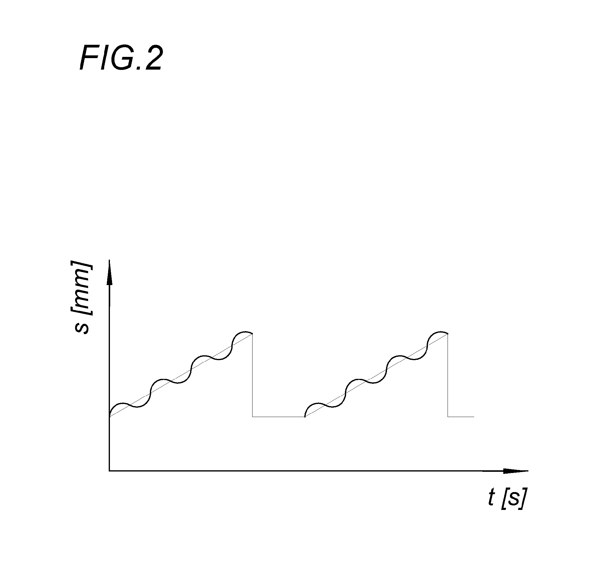
The invention allows for different modes of tamping using various frequencies and amplitudes for different picks. The system can record the actual distances and setpoints, allowing for quality control of the compaction. The system can also react to changes in the ballast bed conditions and automatically adjust the feed speed and amplitude accordingly. This results in a more efficient and effective tamping process.

Problems solved by technology

The technical problem addressed in this patent is the high cost and maintenance of tamping assemblies used for compacting ballast in track beds. The current solutions require frequent overhauls and replacement, and the compaction effect is reduced due to decreasing amplitudes and elasticity of hydraulic hoses. The patent aims to provide a solution that reduces maintenance costs and improves the compaction effect.

Method used


Image

  • Tamping unit for a track tamping machine
  • Tamping unit for a track tamping machine
  • Tamping unit for a track tamping machine

Examples


Embodiment Construction

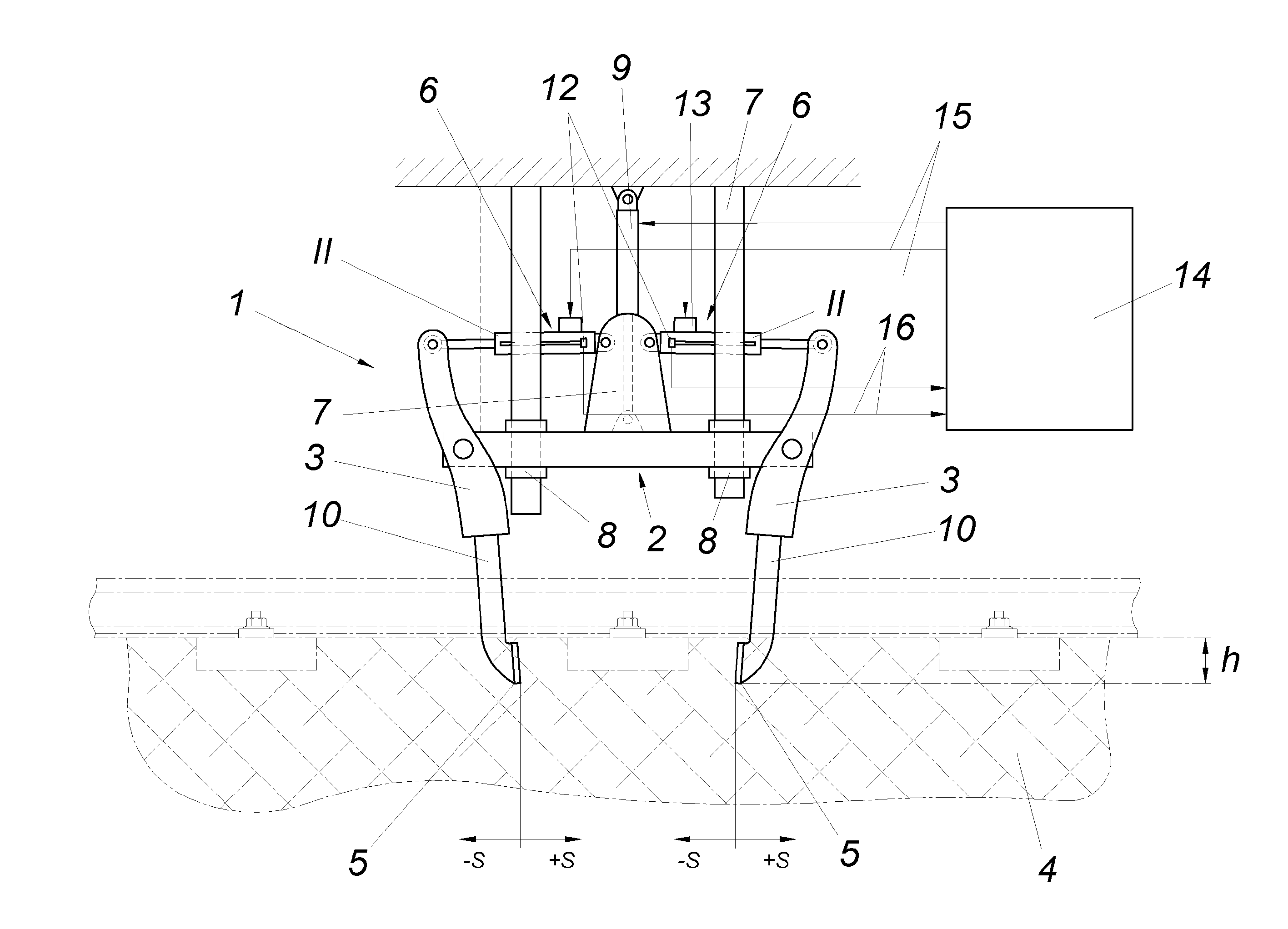
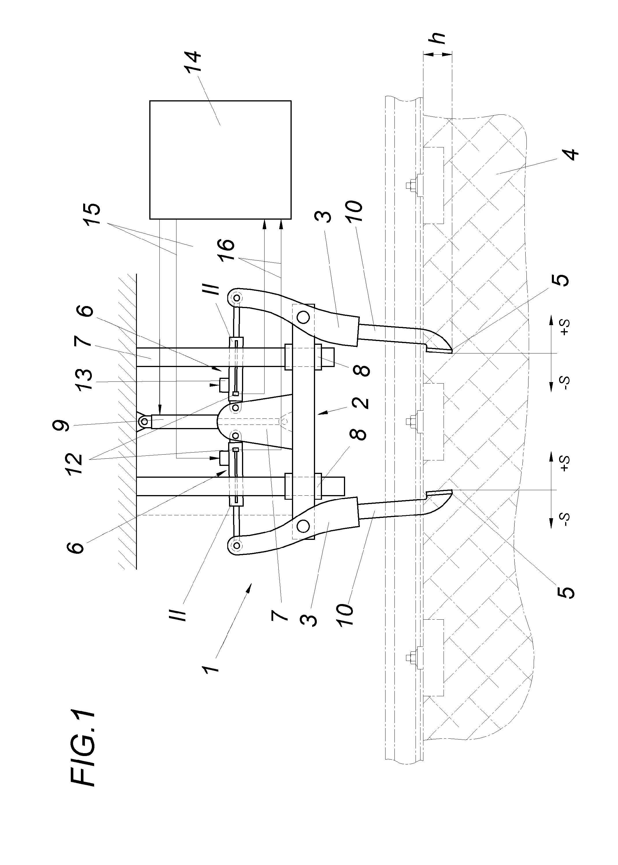
[0019]A tamping assembly 1 for a track tamping machine comprises, inter alia, a pair of tamping tools, which is arranged on a carrier 2 and is designed as a rocker arm, having tamping tools 3, the lower tamping pick ends 5 of which, which are intended to plunge into a ballast bed 4, are drivable in opposite directions using an oscillation drive 6 and can be fed hydraulically toward one another, with a feed distance s. The carrier 2 is guided so it is vertically adjustable in a tamping assembly frame 7 having guides 8 and is displaceable into the desired vertical location using a positioning cylinder 9. The tamping tools 3 are designed as two-armed levers, which are mounted so they are pivotable on the carrier 2. One arm of the respective tamping tool 3 is formed by a tamping pick 10 and a hydraulic cylinder 11 engages on the other arm, which is in turn mounted at the other end on the carrier 2.

[0020]A hydraulic cylinder 11 and a distance sensor 12 for determining the hydraulic cylin...


PUM


Abstract

A tamping assembly for a track tamping machine has a pair of tamping tools arranged on a carrier (2) so it is vertically adjustable in a tamping assembly frame and is designed as a rocker arm, the lower tamping pick ends (5) of which, which plunge into a ballast bed (4), are drivable in opposite directions using an oscillation drive (6) and can be fed hydraulically toward one another. To increase the stability of the tamping assembly, a hydraulic cylinder (11) and a distance sensor (12) for determining the hydraulic cylinder position are associated with each of the tamping tools (3) of a tamping tool pair, wherein the hydraulic cylinders (11) form the feed drive and also the oscillation drive (6) of the tamping tools (3) and the hydraulic cylinders (11) are activated in dependence on the distance sensor signal.

Description


Claims


Application Information

Patent Timeline
Owner HP3 REAL GMBH
Learn More