Self-powered illumination assembly

a self-powered, vehicle-based technology, applied in the direction of other compartment lighting, with built-in power, lighting support devices, etc., can solve the problem of wasted generated vibration energy when not captured and utilized

Active Publication Date: 2016-01-14
NISSAN MOTOR CO LTD
View PDF13 Cites 8 Cited by
  • Summary
  • Abstract
  • Description
  • Claims
  • Application Information

AI Technical Summary

Problems solved by technology

The generated vibration energy is wa

Method used


Image

  • Self-powered illumination assembly
  • Self-powered illumination assembly
  • Self-powered illumination assembly

Examples


Embodiment Construction

[0020]Selected exemplary embodiments will now be explained with reference to the drawings. It will be apparent to those skilled in the art from this disclosure that the following descriptions of the exemplary embodiments are provided for illustration only and not for the purpose of limiting the invention as defined by the appended claims and their equivalents.

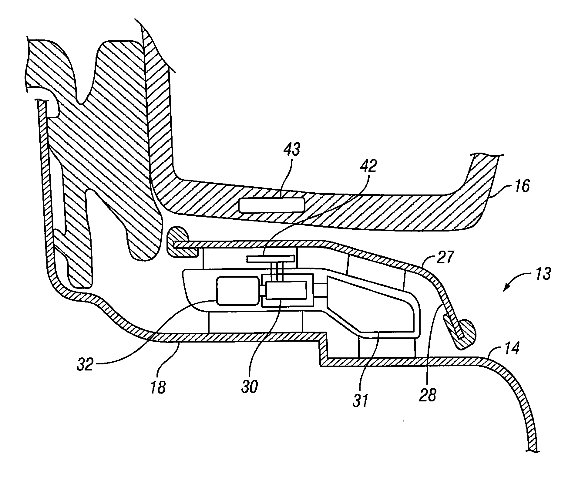
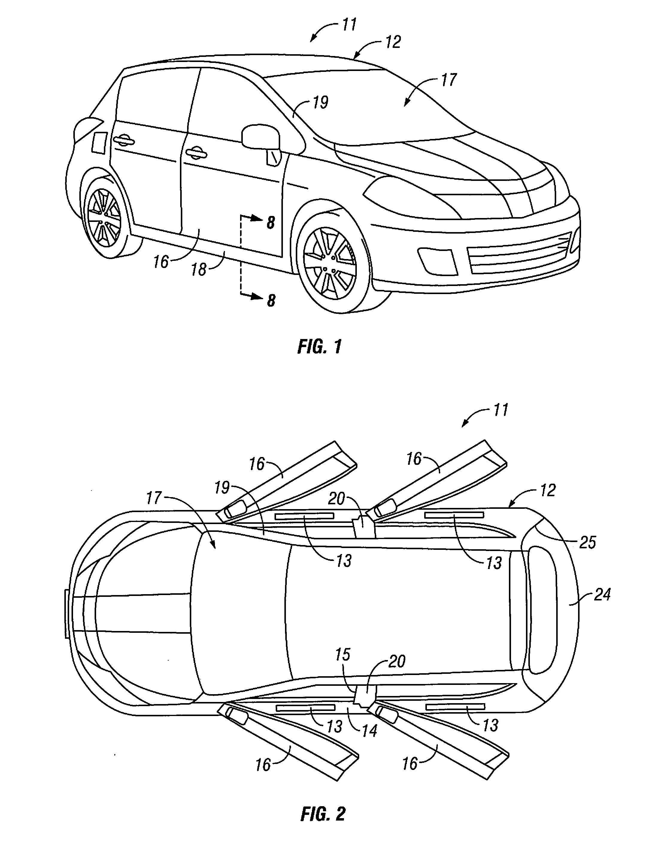
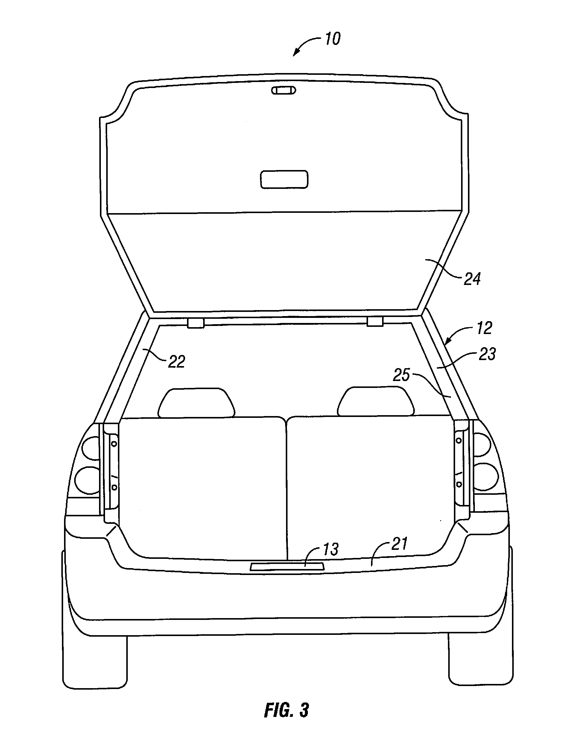
[0021]Referring initially to FIG. 1, a vehicle 11 including a vehicle body structure 12 is illustrated in accordance with an exemplary embodiment of the present invention. As shown in FIG. 2, the vehicle 11 is provided with a plurality of illumination assemblies 13, with one of the illumination assemblies 13 being installed along, for example, a surface 14, where the surface 14 at least partially defines an opening 15 in the vehicle body structure 12. As described below, a plurality of illumination assemblies 13 can be installed at a variety of locations of the vehicle body structure 12.

[0022]As described in greater detail belo...


PUM


Abstract

A self-powered illumination assembly for a vehicle includes a closure panel and a sill protector mounted adjacent to the closure panel. An energy harvesting device is configured to convert ambient energy to electrical energy. A storage device is electrically connected to the energy harvesting device to store the electrical energy. An illumination member is electrically connected to the storage device and is configured to be illuminated by electrical energy supplied from the storage device. A sensor is connected to the sill protector and is configured to supply the stored electrical energy to the illumination member when movement of the closure panel is detected.

Description

BACKGROUND[0001]1. Field of the Invention[0002]The present invention generally relates to a self-powered illumination assembly for a vehicle. More specifically, the present invention relates to a self-powered illumination assembly for a vehicle including an energy harvesting device configured to convert ambient energy to electrical energy and a storage device configured to store and supply electrical energy.[0003]2. Background Information[0004]Passenger vehicles generate vibration energy by movement on a road. The generated vibration energy is wasted when not captured and utilized. Accordingly, a need exists for an energy harvesting device that captures and utilizes vibration energy generated by movement of a vehicle.SUMMARY[0005]In view of the state of the known technology, one aspect of the present invention includes a self-powered illumination assembly for a vehicle. A sill protector is mounted adjacent to a closure panel. An energy harvesting device is configured to convert ambi...

Claims


Application Information

Patent Timeline
IPC IPC(8): F21S9/04B60Q1/50F21K99/00F21S8/10F21V23/04H02N2/18
CPCF21S9/04H02N2/186F21S48/00B60Q1/503F21V23/0471F21V23/045F21K9/30B60Q3/82B60Q3/51B60Q3/217B60Q3/30
Inventor JOHNSON, RANDALLSURA, BHARGAV
Owner NISSAN MOTOR CO LTD
Why Eureka
Try Eureka