Laser tracker calibration system and methods

a laser tracker and calibration system technology, applied in the direction of optical radiation measurement, instruments for comonautical navigation, instruments, etc., can solve the problems of critical measurement errors of even one tenth of an inch, time-consuming and difficult, and precise and accurate movement of an artifact to a specific position and orientation, etc., to achieve quick and easy alignment, sufficient alignment

Active Publication Date: 2016-01-14
BRUNSON INSTR
View PDF2 Cites 12 Cited by
  • Summary
  • Abstract
  • Description
  • Claims
  • Application Information

AI Technical Summary

Benefits of technology

[0014]The present invention pertains generally to a laser tracker calibration and testing system and a method of quickly and easily verifying the accuracy of a laser tracker. Particularly, the present invention pertains to positioning and holding measuring points, such as laser targets, in a particular configuration. In one embodiment, a spherically mounted retro-reflective laser tracker target (SMR) is coupled to an artifact such that positioning and holding the SMR in a particular configuration is accomplished by moving the artifact to, and holding the artifact in, a particular orientation.
[0028]With nominal manufacturing tolerances, the present invention enables sufficient alignment to meet buck-in requirements to isolate the ranging system of the tracker. As a result, wear and tear on the tracker is reduced because the traditional procedure of re-locating the tracker in-line with the virtual centers of the targets is eliminated.

Problems solved by technology

In many such applications, measurement errors on the order of even one ten-thousandth of an inch can be critical.
Precise and accurate movement of an artifact to a specific position and orientation is time consuming and difficult.
Consequently, positioning repeatability is also time consuming and difficult.
Once in position, maintaining the position and orientation of the artifact can be difficult.
A fixture may solve some of these problems, but a fixture also creates additional uncertainty with the accuracy of the reference length.
Unfortunately, several factors, such as “fixturing effects,” create uncertainty as to the accuracy of a reference length “Fixturing effects” may include, but are not limited to, gravity effects, loading effects, and mounting constraint effects.
Additionally, uncertainty of the artifact temperature and uncertainty of the coefficient of thermal expansion of the artifact material create uncertainty with the thermal expansion correction values (if used).
Accordingly, fixturing effects may be difficult to detect and / or to predict.
Thermal expansion restraint creates additional uncertainty with the thermal expansion correction values.
Cantilever bending creates additional uncertainty with the calibrated length of the artifact at various orientations.

Method used


Image

  • Laser tracker calibration system and methods
  • Laser tracker calibration system and methods
  • Laser tracker calibration system and methods

Examples


Embodiment Construction

[0094]As required, a detailed embodiment of the present invention is disclosed herein; however, it is to be understood that the disclosed embodiment is merely exemplary of the principles of the invention, which may be embodied in various forms. Therefore, specific structural and functional details disclosed herein are not to be interpreted as limiting, but merely as a basis for the claims and as a representative basis for teaching one skilled in the art to variously employ the present invention in virtually any appropriately detailed structure.

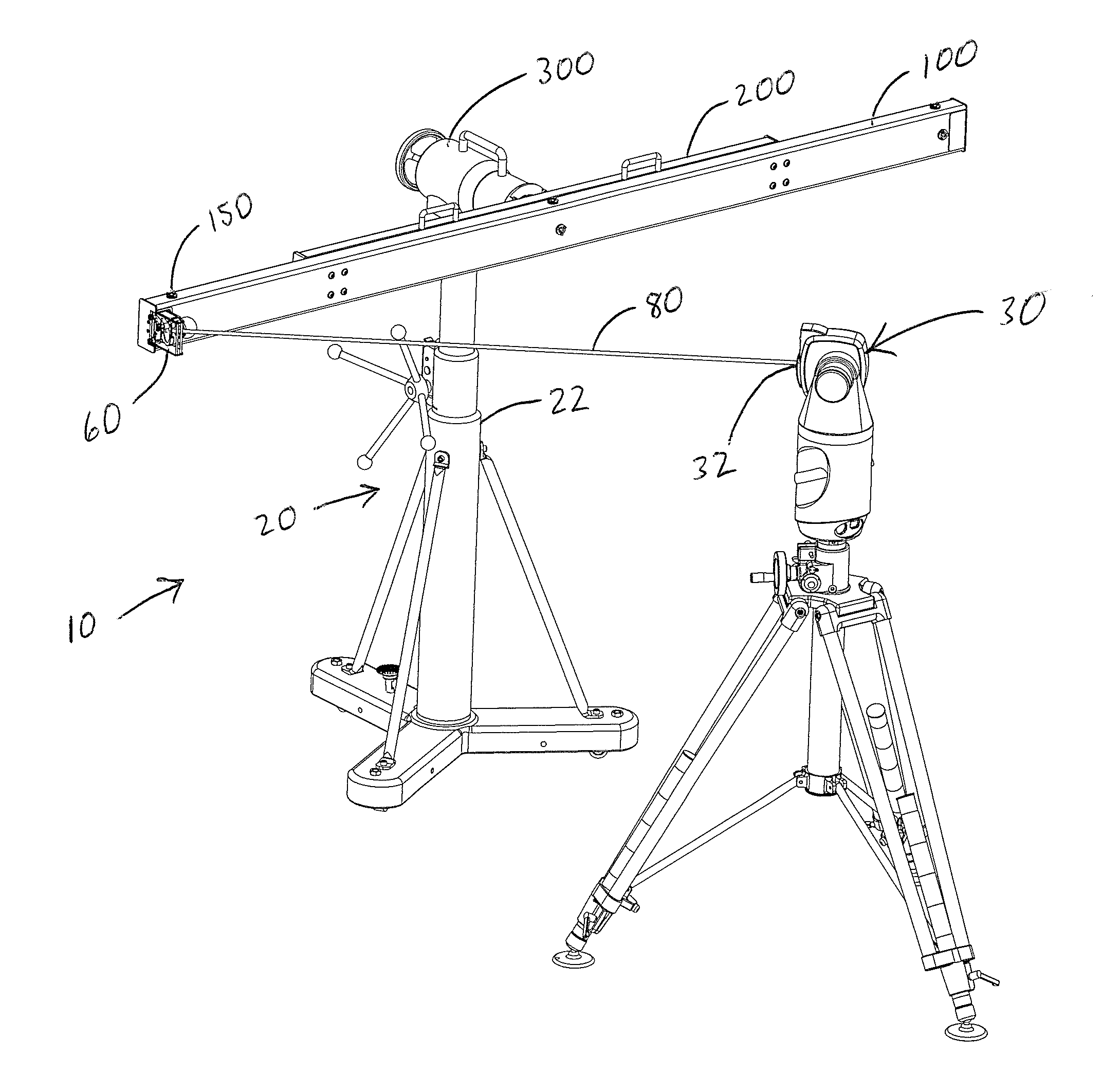
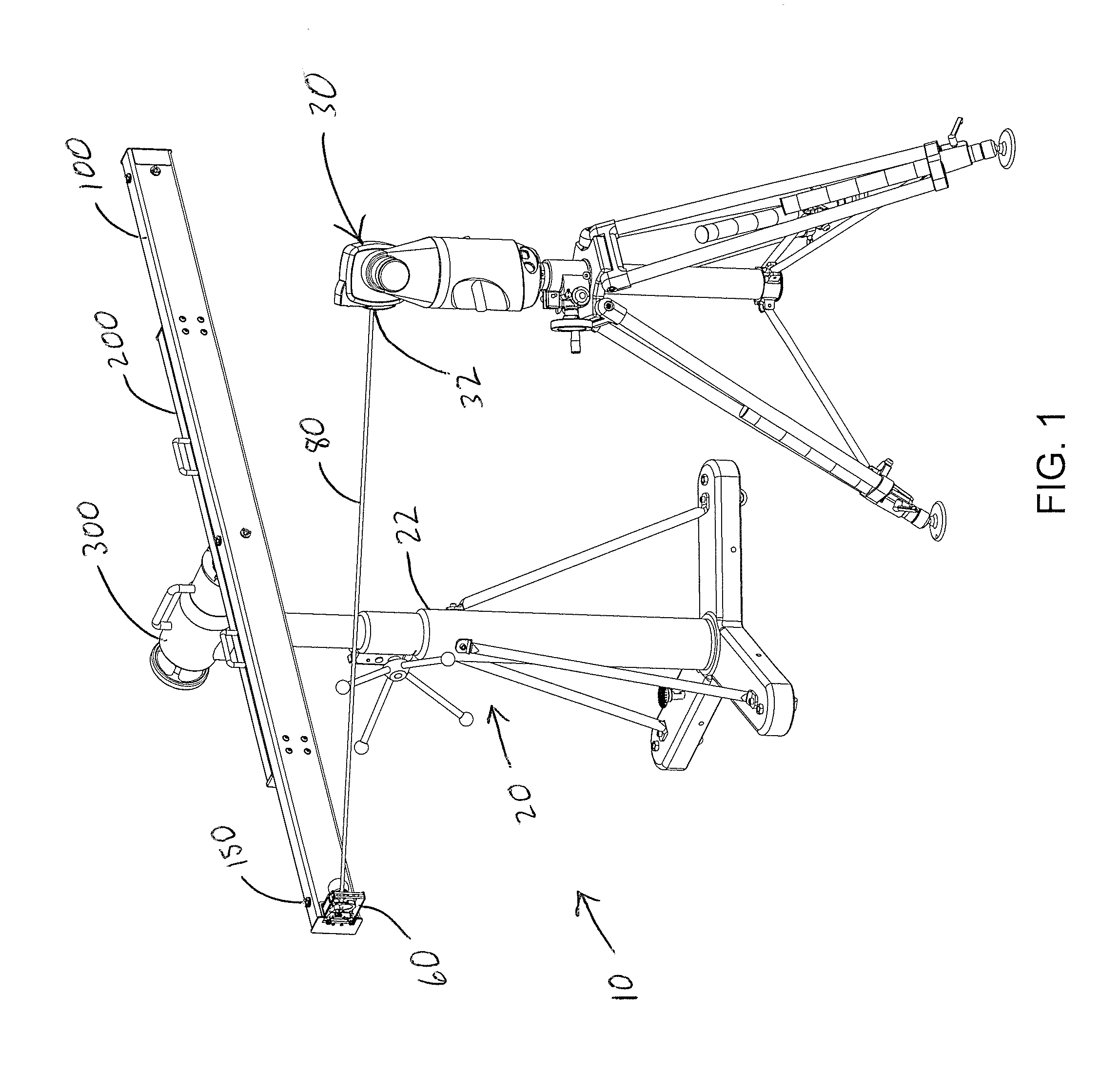
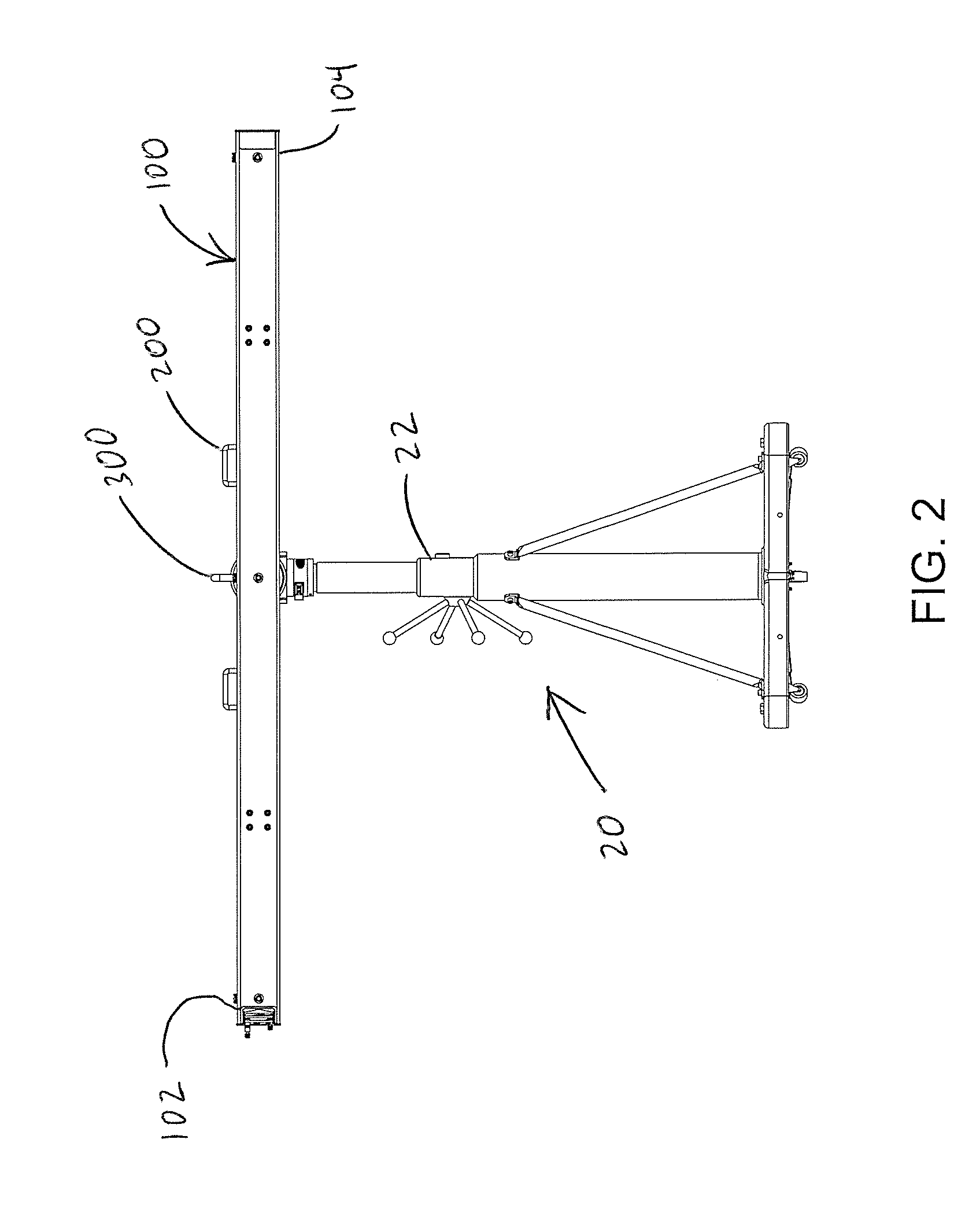
[0095]Referring to FIG. 1, the laser tracker calibration and testing system 10 of the present invention includes an artifact 100 and a support system 20 for the artifact. In some embodiments, the artifact 100 is a hollow rectangular beam that is constructed from a light-weight but rigid composite material that has a low coefficient of thermal expansion. In this way, the artifact remains portable while minimizing deformations. In some such embo...


PUM


Abstract

A system and method of calibrating a laser tracker is provided. The system includes a support system for quickly and easily moving an artifact to a desired position and orientation and for holding the artifact in the position and orientation. An adjustable alignment mirror is coupled to a first end of the artifact so that the more accurate ranging system of the laser tracker can be isolated to determine a reference length of the artifact. Additional measurements are then taken to exercise one or more error source within the tracker. The support system includes a positioner and a support beam for positioning and supporting the artifact. The artifact is coupled to the support beam using kinematic clamps that are designed to reduce or eliminate errors associated with over-constraining the artifact.

Description

CROSS-REFERENCE TO RELATED APPLICATIONS[0001]This application claims priority pursuant to 35 U.S.C. 119(e) to co-pending U.S. Provisional Patent Application Ser. No. 62 / 022,917, filed Jul. 10, 2014, the entire disclosure of which is incorporated herein by reference.FIELD OF THE INVENTION[0002]The present invention relates generally to calibration devices for measuring equipment. More specifically, the present invention is concerned with a system and method for calibrating high precision measuring instruments, such as laser trackers and the like.BACKGROUND OF THE INVENTION[0003]A large number of industries require precise and accurate measuring for a number of applications such as production, manufacturing, and process control. In many such applications, measurement errors on the order of even one ten-thousandth of an inch can be critical. Often, especially when measuring the dimensions of large objects or a long distance between two objects, special equipment and / or instruments are ...

Claims


Application Information

Patent Timeline
Patent Type & Authority Applications(United States)
IPC IPC(8): G01S7/497G01S17/66
CPCG01S17/66G01S7/497G01B21/042G01B11/02
Inventor HUDLEMEYER, AARON A.MEURET, MARK J.
Owner BRUNSON INSTR
Why Eureka
Try Eureka