
Guide rail rope deflection inhibition mechanism and method for parallel soft cable suspension system

Inactive Publication Date: 2016-01-21
CHINA UNIV OF MINING & TECH
View PDF3 Cites 5 Cited by
  • Summary
  • Abstract
  • Description
  • Claims
  • Application Information

AI Technical Summary

Benefits of technology

The present invention is a guide rail rope deflection inhibiting mechanism that improves the running stability and safety of a lifting container. It is a self-actuated pure mechanical structure that does not need electric power or hydraulic drive. It only semi-embraces the guide rail rope and can be installed synchronously in the construction process, saving construction time. It has a damping function and is stable in transition. The guide rail rope deflection inhibiting mechanism is easy to manufacture, install, and disassemble and reassemble. Overall, it is an effective solution for improving safety and efficiency in construction projects.

Problems solved by technology

If the pretension of the guide rail rope of the suspension guiding system is too small, the lifting container will have a severe deflection or even turn over when it runs along the guide rail rope, which endangers life safety of the construction workers.
However, that specification can not be met solely by means of the dead weight of the guide frame; otherwise the deflection of the lifting container will be very severe; even though the pretension meets the requirement, the steel wire rope can't be selected among standard products because of the extremely high pretension, under the constraints of tensile strength and safety factor.
In summary, it is difficult to inhibit the deflection of guide rail rope in a parallel flexible cable suspension system, which brings a severe risk to the safety of construction of ultra-deep vertical shafts.

Method used


Image

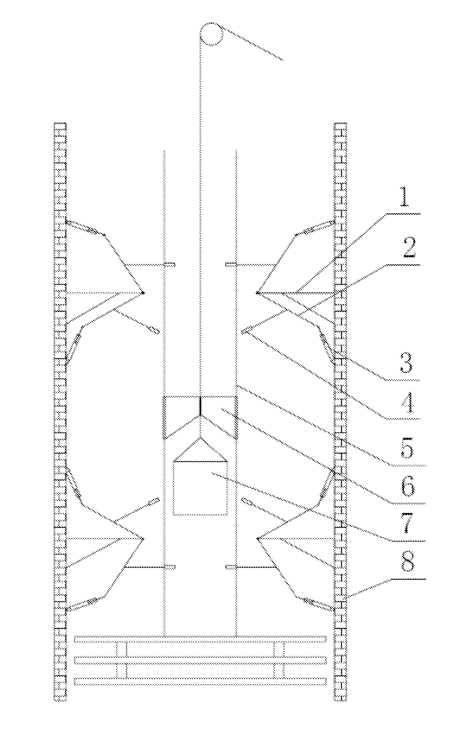
  • Guide rail rope deflection inhibition mechanism and method for parallel soft cable suspension system
  • Guide rail rope deflection inhibition mechanism and method for parallel soft cable suspension system
  • Guide rail rope deflection inhibition mechanism and method for parallel soft cable suspension system

Examples


Embodiment Construction

[0020]Hereunder the present invention will be further detailed with reference to the accompanying drawings.

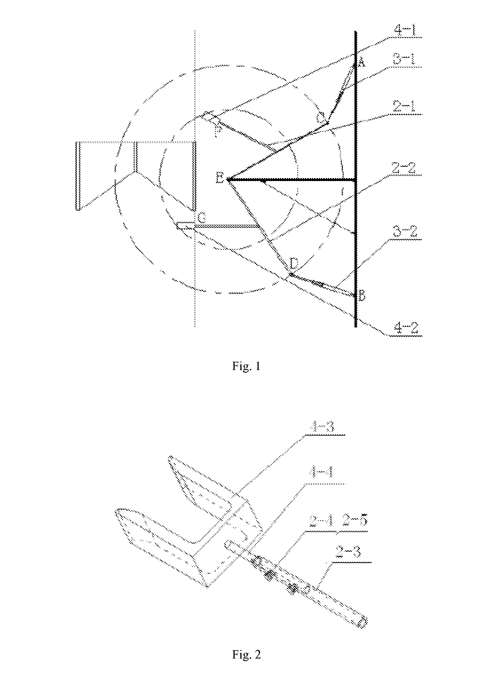
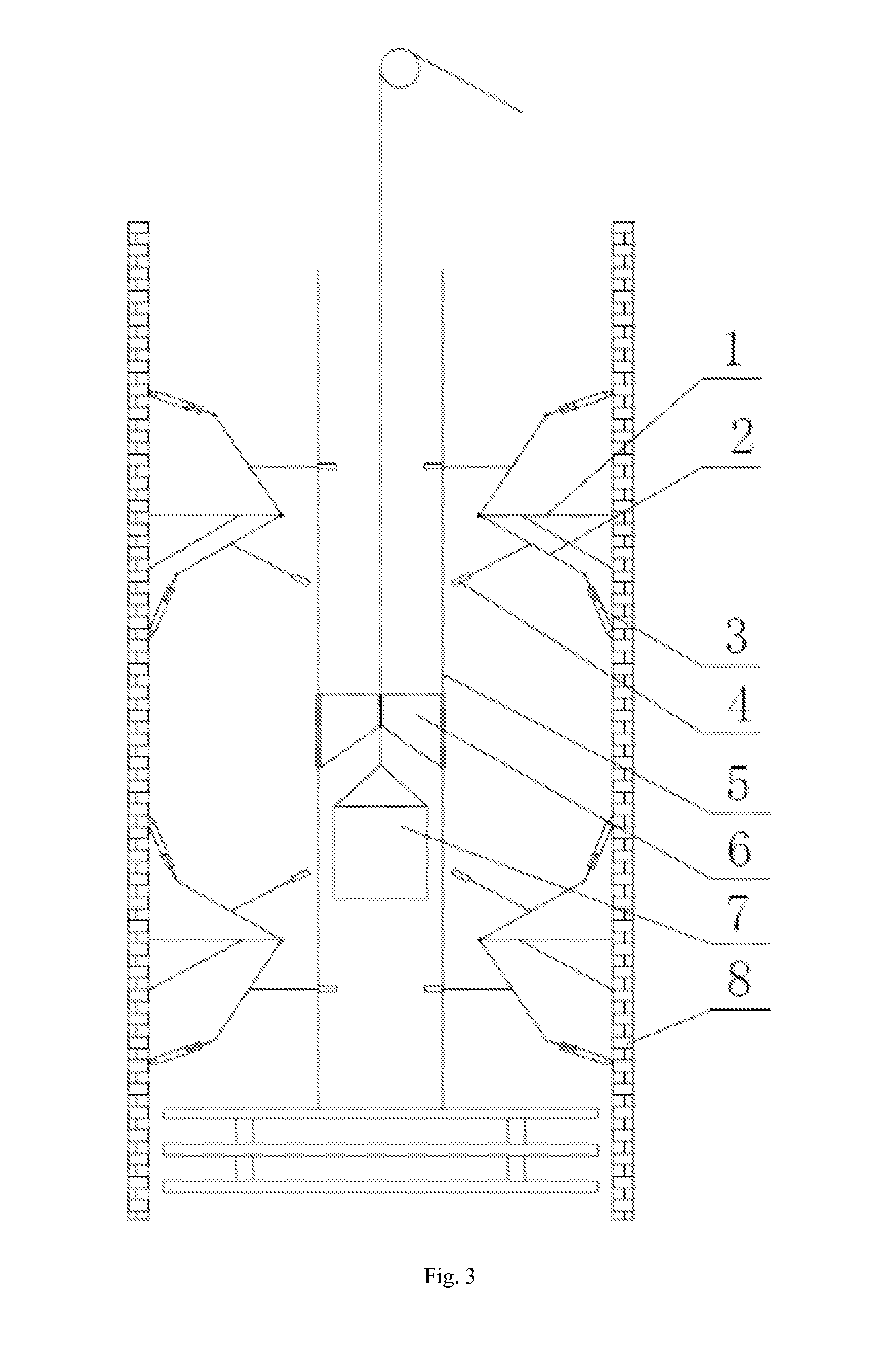
[0021]As shown in FIG. 1 and FIG. 2, the guide rail rope deflection inhibiting mechanism for a parallel flexible cable suspension system according to the present invention comprises a ‘T’-shaped mounting support 1, a rotary frame 2, a hydraulic supporting rod 3 and a chuck 4.

[0022]The ‘T’-shaped mounting support 1 comprises a longitudinal supporting rod and a transverse supporting rod, the longitudinal supporting rod is fixed on the shaft wall 8, and one end of the transverse supporting rod is fixed to the center of the longitudinal supporting rod. The hydraulic supporting rod 3 comprises an upper hydraulic supporting rod 3-1 and a lower hydraulic supporting rod 3-2, one end of the upper hydraulic supporting rod 3-1 is hinged to the upper end (end A in the figures) of the longitudinal supporting rod, and one end of the lower hydraulic supporting rod 3-2 is hinged to the lower e...


PUM


Abstract

A guide rail rope deflection inhibition mechanism and method for a parallel soft cable suspension system in ultradeep vertical shaft construction. The guide rail rope deflection inhibition mechanism comprises a T-shaped installation support base, a rotating frame, a hydraulic support rod, and a chuck. The T-shaped installation support base comprises a vertical support rod and a horizontal support rod. The hydraulic support rod comprises an upper hydraulic support rod and a lower hydraulic support rod. The rotating frame comprises an upper Y-shaped frame and a lower Y-shaped frame. The chuck comprises an upper chuck and a lower chuck. The guide rail rope deflection inhibition method treats two guide rail rope deflection inhibition mechanisms as one group, and arranges at least two groups along the vertical direction on the shaft wall. While guaranteeing the smooth sliding of a direction guiding frame, the freedom of the guide rail rope part is restrained by the chuck, thereby enhancing the stability and safety of hoisting containers.

Description

FIELD OF THE INVENTION[0001]The present invention relates to construction equipment for mine shafts and drifts, in particular to a guide rail rope deflection inhibiting mechanism and a method for a parallel flexible cable suspension system, which are applicable to construction of ultra-deep vertical shafts.BACKGROUND OF THE INVENTION[0002]As shallow and semi-deep mineral resources are depleted gradually in China, exploiting deep resources has become an inevitable choice for ensuring sustainable development of the national economy. Therefore, it is imperative to excavate ultra-deep vertical shafts, and that mission brings higher requirements for safe transportation of personnel and materials. At present, most guide frames for deep vertical shaft construction employ two suspension ropes also as guide rail ropes, which are pre-tensioned by the dead weight of the guide frame. Such a system belongs to a typical parallel flexible cable suspension guiding system, which is mainly designed t...

Claims


Application Information

Patent Timeline
IPC IPC(8): E21D7/02B66B7/02B66B17/00
CPCE21D7/02B66B7/02B66B17/00
Inventor CAO, GUOHUAWANG, JINJIEZHU, ZHENCAIPENG, WEIHONGWANG, YANDONGZHANG, LEISHEN, GANGLIU, SHANZENG
Owner CHINA UNIV OF MINING & TECH
Learn More