Toy projectile launchers with two trigger safety locks

a technology of safety locks and toy launchers, which is applied in the field of safety locks for toy launchers, can solve problems such as danger to the user of toy launchers, and achieve the effect of simple construction and fun us

Active Publication Date: 2016-01-21
HASBRO INC
View PDF11 Cites 26 Cited by
  • Summary
  • Abstract
  • Description
  • Claims
  • Application Information

AI Technical Summary

Benefits of technology

[0008]The slide lock element engages the trigger lock element to prevent trigger movement until the cocking slide is safely out of the way of the rapidly moving energy generating mechanism. This is done to prevent contact between a rapidly moving energy generating mechanism that is snapping back from a cocked position once the trigger is pulled and the toy launcher cocking slide. Inadvertent contact may create a danger to the user of the toy launcher. To prevent the discharge of an improperly configured projectile, the projectile lock element engages the trigger lock element to prevent trigger movement until a properly configured projectile is loaded in the toy launcher. Once a properly configured projectile is loaded, the projectile moves the projectile lock element from engagement with the trigger lock element thereby allowing the trigger to become operable.
[0009]When both the slide lock element and the projectile lock element are disengaged from the trigger lock element, the trigger is freed to move the trigger lock element whereby the energy generating mechanism is released. More particularly, the objects of the present invention are first, to prevent inadvertent contact between the toy launcher cocking slide and the released energy generating mechanism which is rapidly returning to a non-cocked position after being cocked, and second, to prevent nonconforming and potentially dangerous projectiles, such as a pencil, from being discharged from the toy launcher. The toy launchers disclosed herein are safe, simply constructed, fun to use, reliable, relatively inexpensive and yet, structurally robust.

Problems solved by technology

Inadvertent contact may create a danger to the user of the toy launcher.

Method used


Image

  • Toy projectile launchers with two trigger safety locks
  • Toy projectile launchers with two trigger safety locks
  • Toy projectile launchers with two trigger safety locks

Examples


Embodiment Construction

[0039]The following description is provided to enable those skilled in the art to make and use the described embodiments set forth in the best mode contemplated for carrying out the invention. Various modifications, equivalents, variations, and alternatives, however, will remain readily apparent to those skilled in the art. Any and all such modifications, variations, equivalents, and alternatives are intended to fall within the spirit and scope of the present invention.

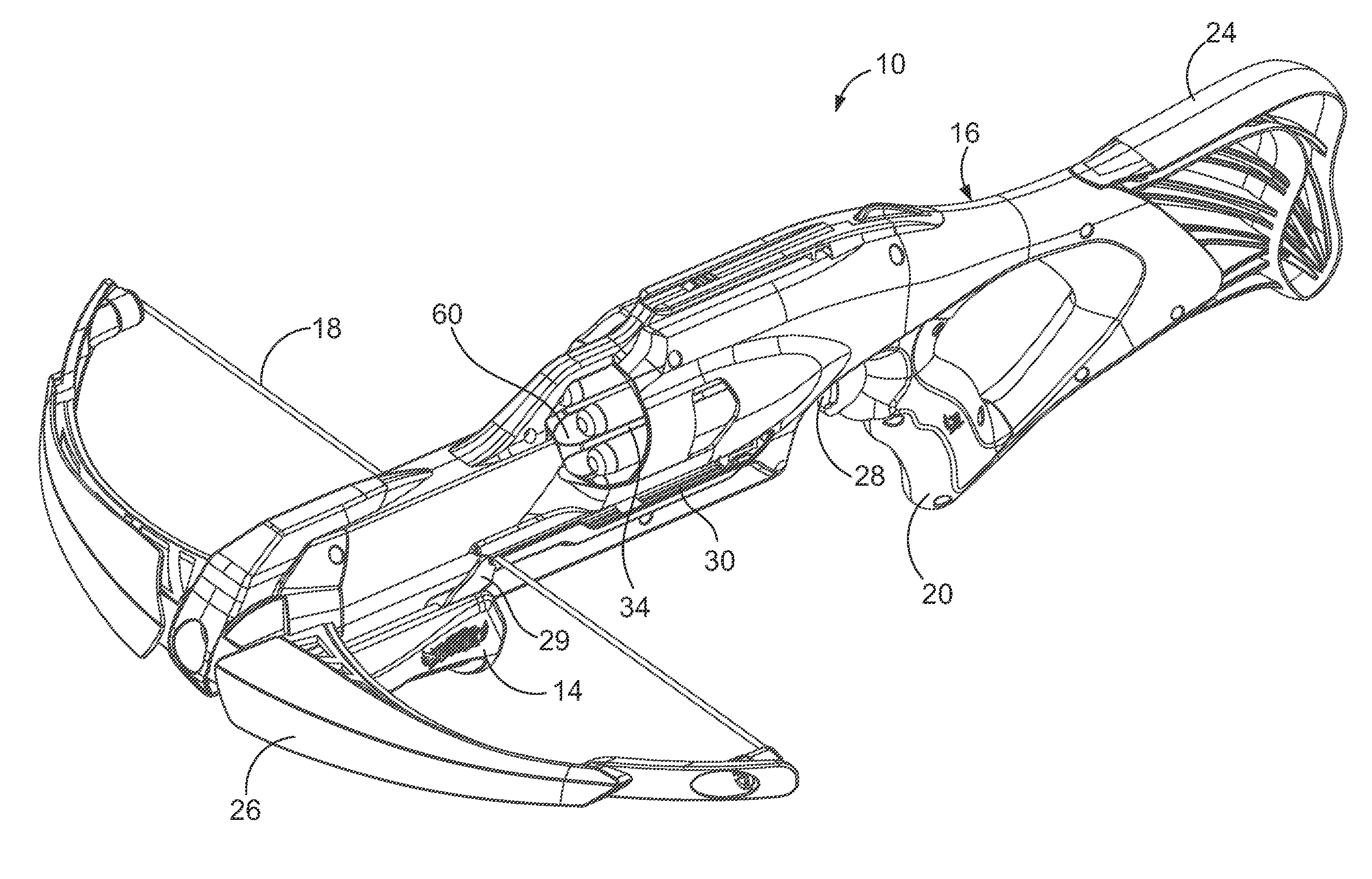
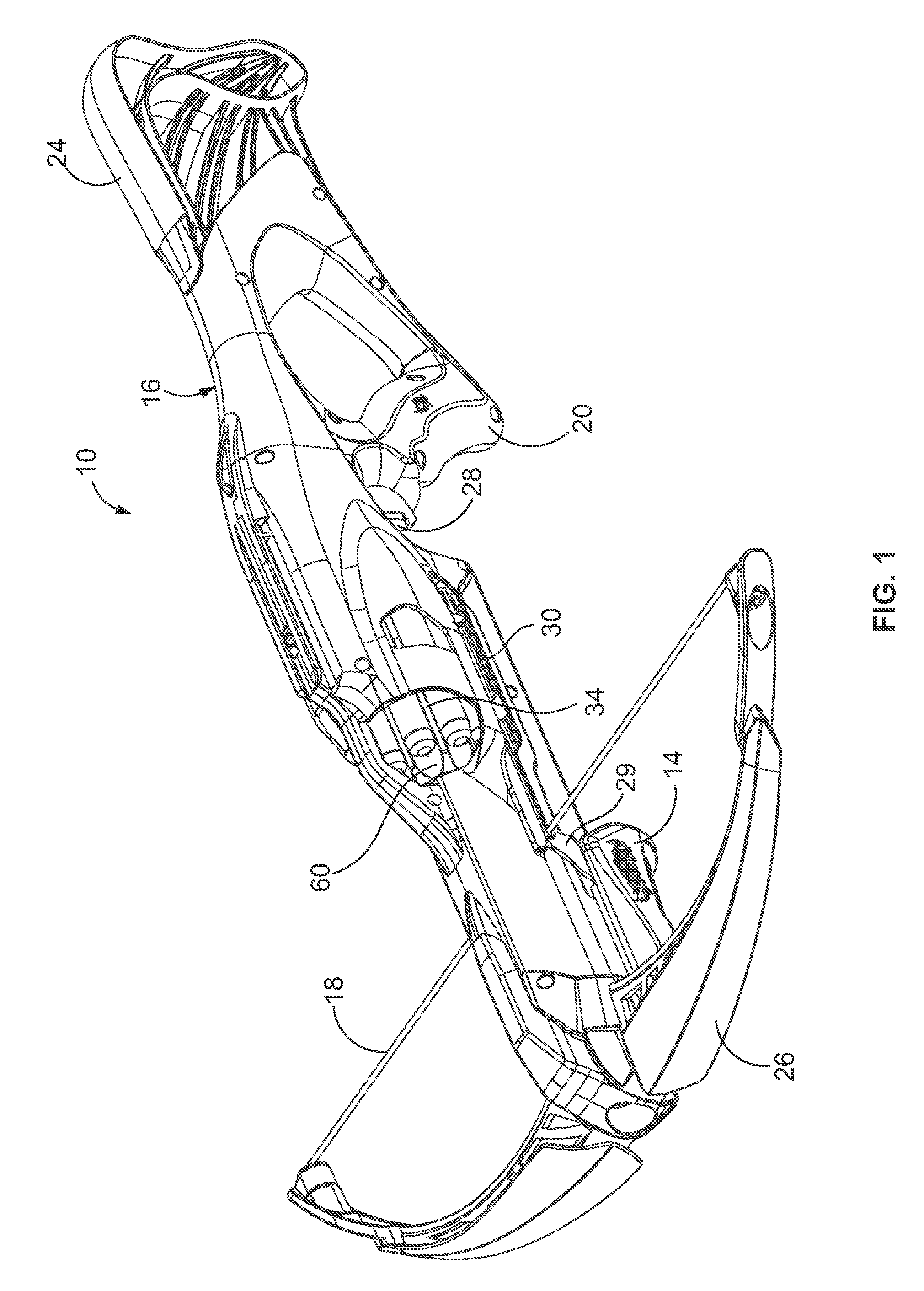
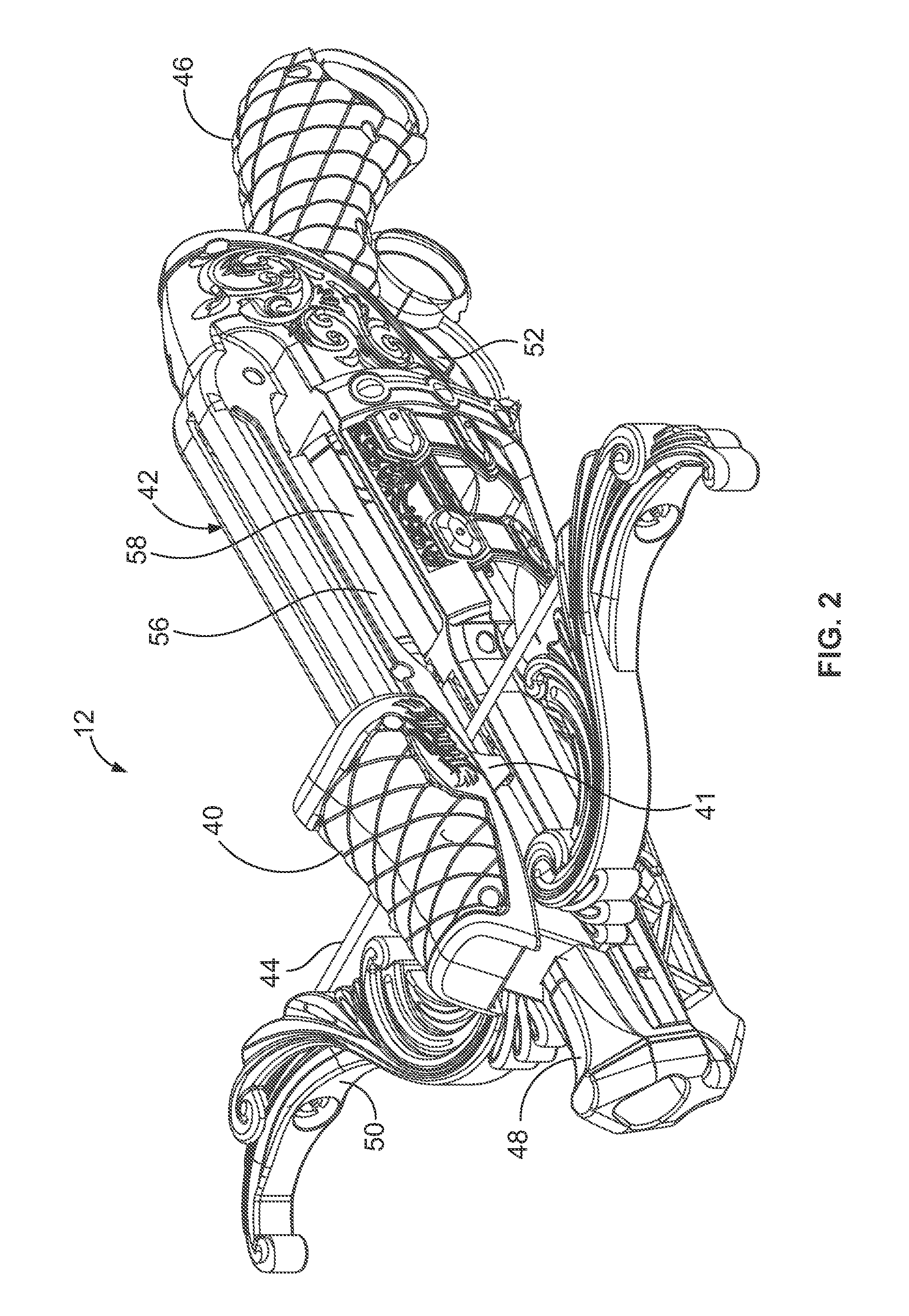
[0040]Referring to FIGS. 1 and 2, there are illustrated two embodiments of toy launch apparatus having trigger safety locks. The first embodiment is in the form of a bottom cocking stylized toy crossbow 10, FIG. 1. The second embodiment is in the form of a top cocking, highly stylized toy crossbow 12, FIG. 2. The bottom cocking toy crossbow 10 includes a cocking slide 14 mounted to a lower portion of an outer housing 16 for moving an energy generating mechanism in the form of a stretchable string or cord 18 from a rel...


PUM

PropertyMeasurementUnit
energyaaaaaaaaaa
heightaaaaaaaaaa
transfer energyaaaaaaaaaa

Abstract

Crossbows having two trigger safety locks. Operatively connected to a trigger is a trigger lock element that in one position prevents the trigger from moving. To prevent inadvertent contact between a cocking slide and a released stretched cord of the crossbow, a slide lock element engages the trigger lock element until the slide lock element is disengaged by the cocking slide moving out of the way. To prevent an improperly configured projectile from being discharged a projectile lock element engages the trigger lock element until a properly configured projectile is loaded onto a drum causing the projectile lock element to disengage from the trigger lock element.

Description

PRIORITY CROSS-REFERENCE TO RELATED APPLICATION[0001]This application claims priority pursuant to 35 U.S.C. 119(e) from U.S. Provisional Patent Application No. 62 / 022,077, filed on Jul. 8, 2014, which Application is expressly incorporated herein by reference.FIELD OF THE INVENTION[0002]The present invention relates generally to safety locks for toy projectile launchers, and more particularly, to toy launchers having two trigger safety locks that prevent cocking slides or handles from inadvertently snapping forward when a trigger is pulled and that prevent improperly configured projectiles from being discharged.BACKGROUND OF THE INVENTION[0003]Concern about discharging improperly configured projectile has been a concern for years. For example, a safety valve appears in a patent issued to Nin and D'Andrade, U.S. Pat. No. 5,515,837, granted in 1996, and entitled “Safety Nozzle For Multi-Shot Projectile Shooting Air Gun,” and in U.S. Pat. No. 5,529,050, also issued in 1996 to D'Andrade ...

Claims


Application Information

Patent Timeline
Patent Type & Authority Applications(United States)
IPC IPC(8): F41A17/30F41A17/46F41B5/12
CPCF41A9/73F41B7/08F41A17/46F41A17/30F41B5/12F41B11/54F41B11/89
Inventor LALLIER, JOHN PAULNUGENT, DAVID MICHAELMERMELSTEIN, KATHERINE A.KESKA, TADEUSZ W.
Owner HASBRO INC
Why Eureka
Try Eureka