
Display panel, array substrate and method for manufacturing the same

a technology of array substrates and display panels, applied in the field of liquid crystal display, can solve the problems of image sticking, poor voltage uniformity along the common line, and rejection ratio, and achieve the effect of improving the uniformity of the optimum common voltage and increasing the quality of the produ

Inactive Publication Date: 2016-01-21
SHENZHEN CHINA STAR OPTOELECTRONICS TECH CO LTD
View PDF4 Cites 5 Cited by
  • Summary
  • Abstract
  • Description
  • Claims
  • Application Information

AI Technical Summary

Benefits of technology

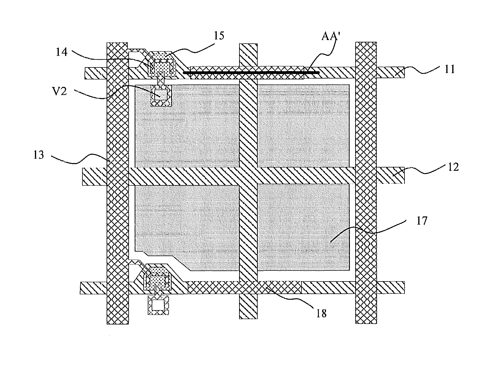
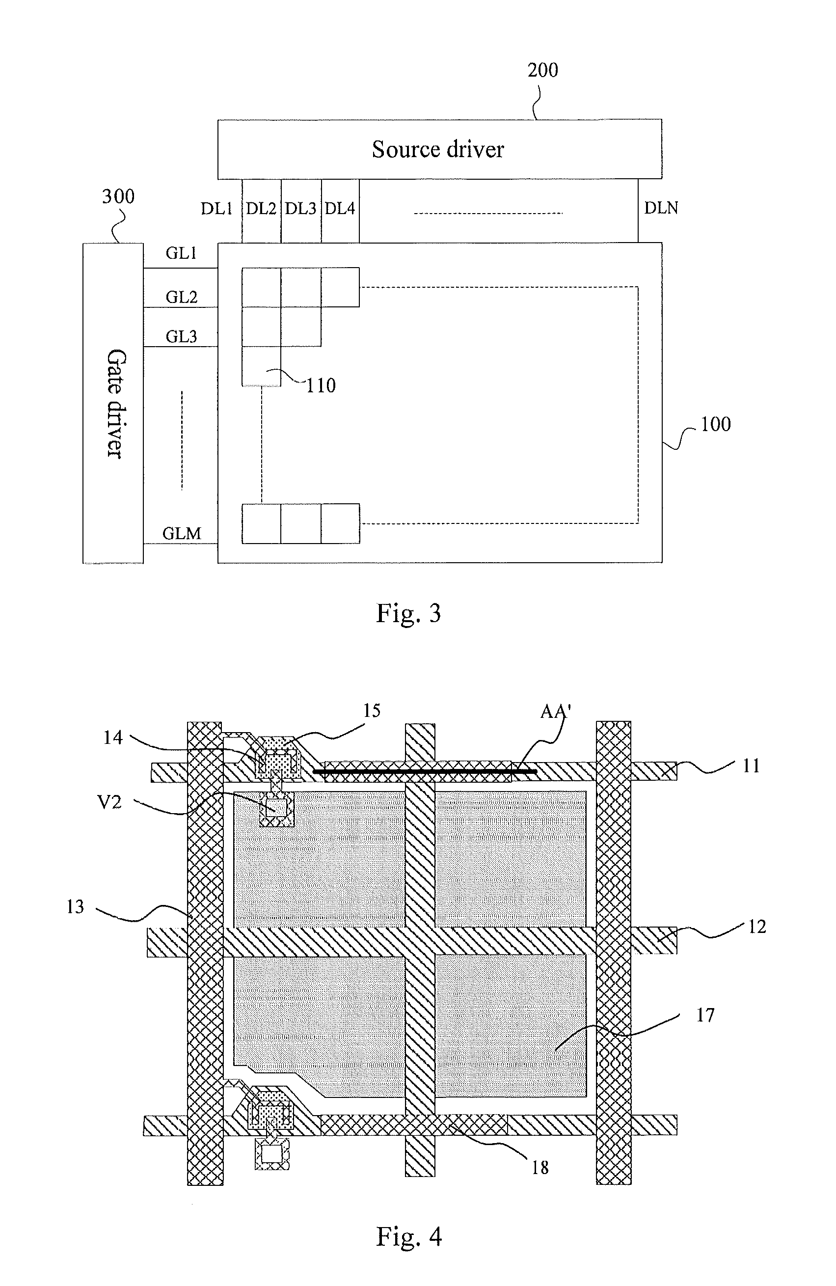
The present patent provides an array substrate with improved uniformity of optimum common voltage and better product quality. The method for manufacturing the array substrate and display panel comprising it are also provided. The technical solution involves interrupting the gate lines in the array substrate and short-circuiting them in the effective display area to improve the conductivity of the common lines. This results in a more uniform voltage and improved product quality.

Problems solved by technology

Therefore, it is a major issue in the art to improve the product quality, reduce the reject ratio, and save cost.
It is found that there are the following defects in the prior art.
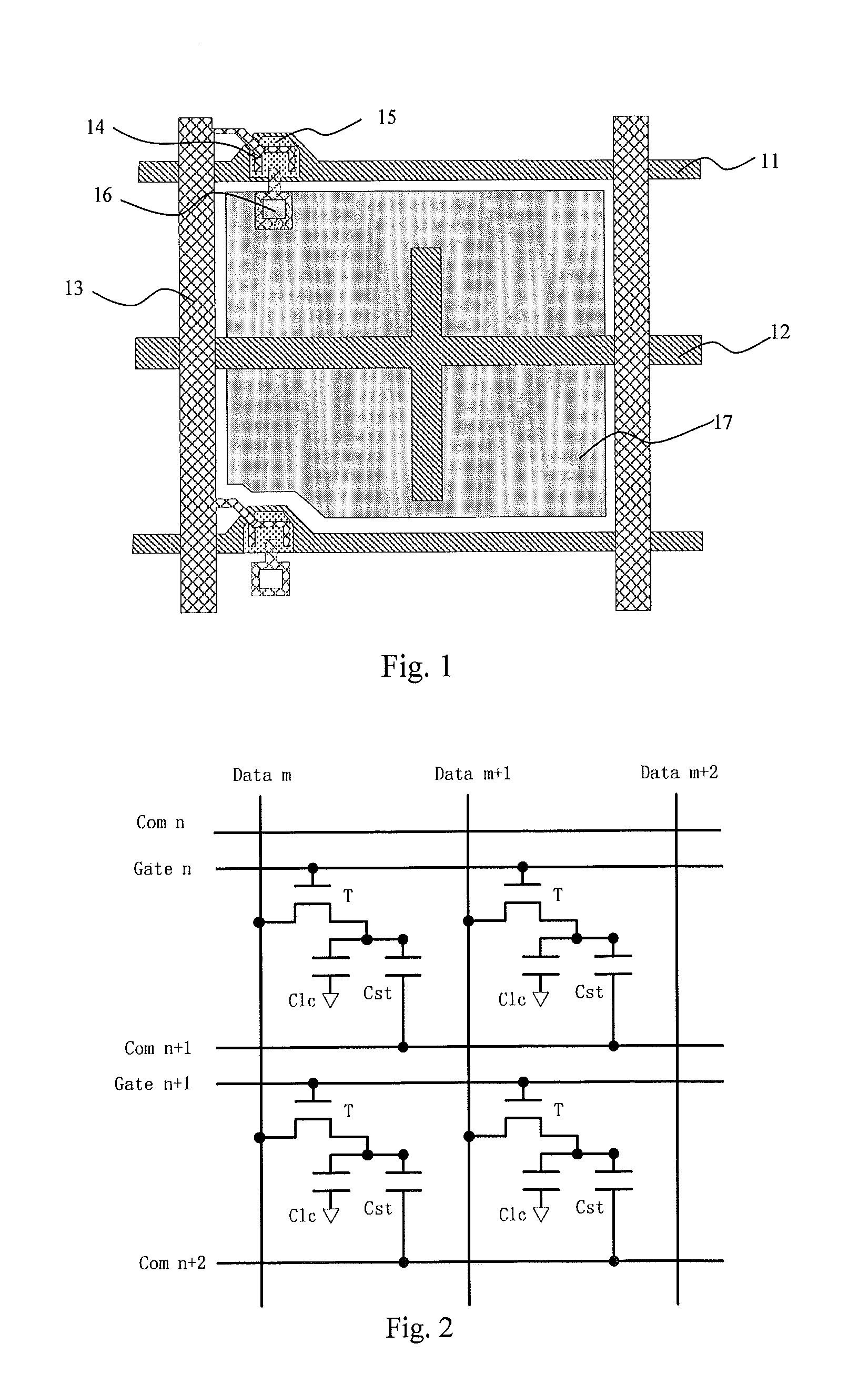
For example, the common voltage at an end of the common line can be larger than that at the center thereof, rendering poor voltage uniformity along the common line.
Consequently, image sticking can easily occur.

Method used


Image

  • Display panel, array substrate and method for manufacturing the same
  • Display panel, array substrate and method for manufacturing the same
  • Display panel, array substrate and method for manufacturing the same

Examples


Embodiment Construction

[0042]The present disclosure will be explained in detail with reference to the embodiments and the accompanying drawings, whereby it can be fully understood about how to solve the technical problem by the technical means according to the present disclosure and achieve the technical effects thereof, and thus the technical solution according to the present disclosure can be implemented. It is important to note that as long as there is no structural conflict, various embodiments as well as the respective technical features mentioned herein may be combined with one another in any manner, and the technical solutions obtained all fall within the scope of the present disclosure.

[0043]The following specific examples, by means of which the present disclosure can be implemented, are explained with reference to the accompanying drawings. The directional terms in the present disclosure, such as up, down, left, and right, etc., merely indicate the directions as shown in the accompanying drawings...


PUM

PropertyMeasurementUnit
yield rateaaaaaaaaaa
voltageaaaaaaaaaa
voltage dropaaaaaaaaaa

Abstract

A display panel, an array substrate, and a method for manufacturing the same are provided. The array substrate comprises a plurality of pixel units each having a gate line and a common line. The gate line comprises a first line segment and a second line segment. An electric connection structure is disposed in the interrupted region between the first line segment and the second line segment, so that the first line segment and the second line segment are electrically connected with each other through the electric connection structure, and the common line extends through said interrupted region in a direction perpendicular to the gate line, and is in insulated contact with the first line segment and the second line segment. The present disclosure can improve the uniformity of the optimum common voltage, thereby improving the product quality.

Description

[0001]The present application claims benefit of Chinese patent application CN 201410348365.3, entitled “Display Panel, Array Substrate and Method for Manufacturing the Same” and filed on Jul. 21, 2014, which is incorporated herein by reference.TECHNICAL FIELD[0002]The present disclosure relates to the technical field of liquid crystal display. Specifically, the present disclosure relates to a display panel, an array substrate, and a method for manufacturing the array substrate.TECHNICAL BACKGROUND[0003]As the information society develops, people's demand for display device grows. As a result, the industry of liquid crystal display panel is booming rapidly. With the increase of the production of liquid crystal display panel, people's demand for the quality and yield rate of the product also becomes higher. Therefore, it is a major issue in the art to improve the product quality, reduce the reject ratio, and save cost.[0004]At present, in designing an array substrate, a common line is...

Claims


Application Information

Patent Timeline
Patent Type & Authority Applications(United States)
IPC IPC(8): G02F1/1362G02F1/1368H01L23/522H01L23/532H01L27/12
CPCG02F1/136286G02F1/1368G02F1/136227G02F2001/136295H01L27/1259H01L23/5226H01L23/53209H01L27/124G02F2201/121G02F1/133397G02F1/136295
Inventor CHAI, LI
Owner SHENZHEN CHINA STAR OPTOELECTRONICS TECH CO LTD
Learn More