
Tube expander with positioning structure

a technology of positioning structure and tube expander, which is applied in the direction of positioning device, metal-working feeding device, manufacturing tool, etc., can solve the problems of increased manpower and time cost, easy damage to tube members, and inability to provide positioning structure, so as to achieve rapid and accurate movement and save time cost

Inactive Publication Date: 2016-01-28
CHAMP AIR REFRIGERATION HARDWARE
View PDF0 Cites 19 Cited by
  • Summary
  • Abstract
  • Description
  • Claims
  • Application Information

AI Technical Summary

Benefits of technology

The present invention provides a positioning device for a tube clamp that allows for accurate positioning of each tube bore under the expanding cone without damaging the tube member during the expanding operation. This saves time and reduces man power costs.

Problems solved by technology

However, the above mentioned tube expander is not provided with any positioning structures for positioning the clamp.
Under the circumstance, if the user still uses the cone head to expand the orifice of the tube member, the tube member tends to be damaged easily.
As a result, known tube expander requires additional man power and time cost for accurately aiming the cone head at the orifice of the tube member for preventing such damage from happening, thus failing to meet the demand of being conveniently operated.

Method used


Image

  • Tube expander with positioning structure
  • Tube expander with positioning structure
  • Tube expander with positioning structure

Examples


Embodiment Construction

[0020]The aforementioned and further advantages and features of the present invention will be understood by reference to the description of the preferred embodiment in conjunction with the accompanying drawings.

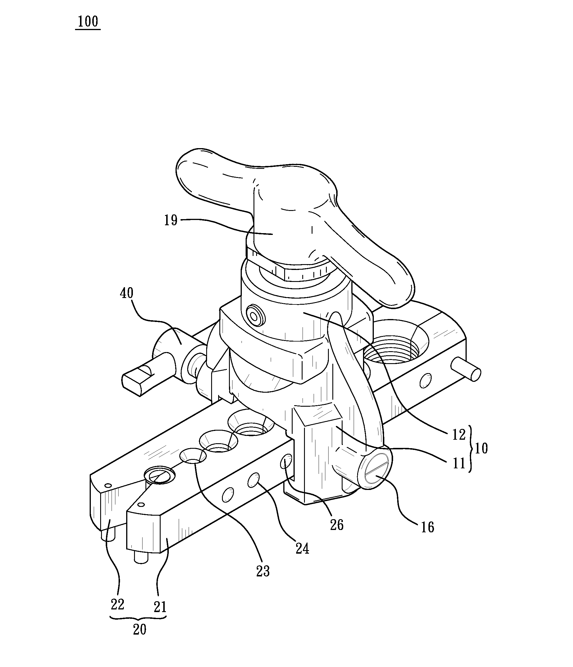
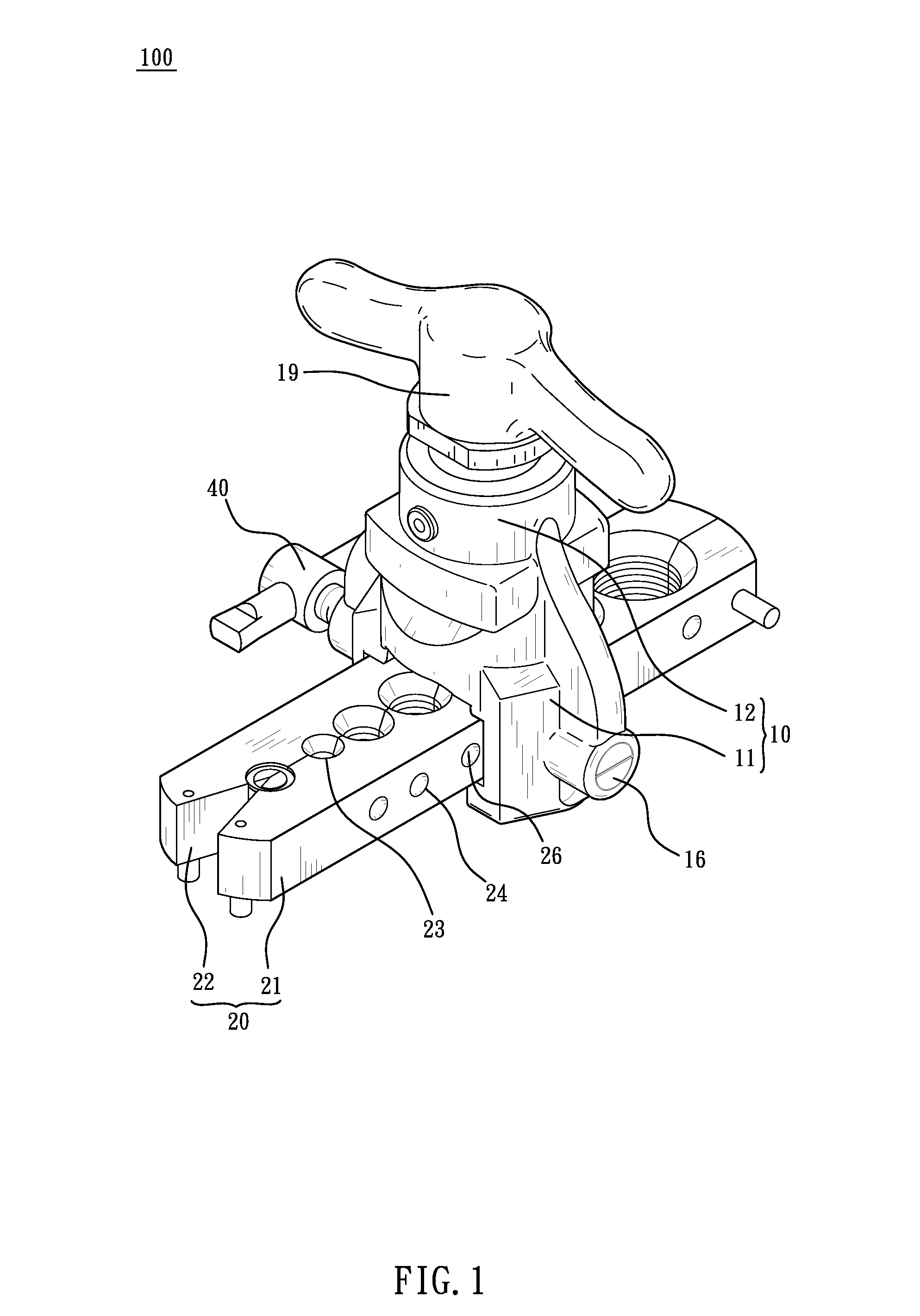
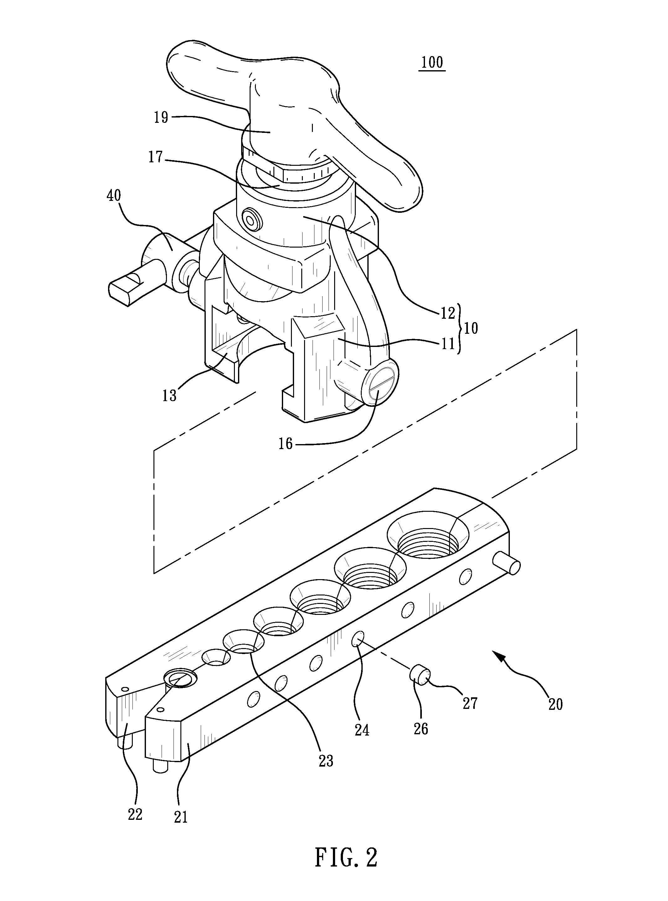
[0021]Referring FIG. 1 to FIG. 5, the present invention provides a tube expander 100 with positioning structure, comprising a base 10, a tube clamp 20, a positioning device 30, and an adjusting thread rod 40.

[0022]The base 10 is made of aluminum, provided with a body 11 and connected to a neck 12 on the top end of the body 11. A guiding groove 13 is transversely disposed on the body 11. A positioning bore 14 is disposed on the wall of the body 11 and at the same time disposed on one side of the guiding groove 13, wherein the positioning bore 14 is connected to the outer face of the body 11 and the guiding groove 13, respectively. An inner thread 15 is disposed on one end of the positioning bore 14 connected with the outer face of the body 11 for receiving a nut 16. A rotating...


PUM

PropertyMeasurementUnit
shapeaaaaaaaaaa
timeaaaaaaaaaa
diameter sizeaaaaaaaaaa

Abstract

A tube expander with positioning structure includes a base, a tube clamp, a positioning device, and an adjusting thread rod. Therein, the base has a body and a neck. The body has a guiding groove and the neck is inserted with a rotating thread rod capable of vertically moving. An expanding cone facing the guiding groove is on one end of the rotating thread rod. The tube clamp having tube bores is slidingly disposed in the guiding groove. The positioning device is on one side of the guiding groove, thereby engaging and positioning the tube clamp and positioning the tube bores under the expanding cone. The adjusting thread rod is pivotally disposed on the body for fastening the tube clamp.

Description

BACKGROUND OF THE INVENTION[0001]1. Field of the Invention[0002]The present invention relates to tube expanders, and more particularly, to a tube expander provided with a positioning structure.[0003]2. Description of the Related Art[0004]When a tube is to be connected to extend or to be installed in a curved section, a tube expander is utilized in a tube expanding process. In most tube expanders, a tube member is usually clamped and fastened by a clamp, and the clamp is placed in a guiding groove of the tube expander, while a cone head of the tube expander is in alignment with the tube member, whereby a handle of the tube expander is rotated for driving the cone head to expand the end part of the tube member, thus expanding the tube orifice of the tube member into a cone shape for facilitating the tube connecting operation.[0005]However, the above mentioned tube expander is not provided with any positioning structures for positioning the clamp. Although an adjusting thread rod is pr...

Claims


Application Information

Patent Timeline
Patent Type & Authority Applications(United States)
IPC IPC(8): B21D43/00B21D39/20B21D41/02
CPCB21D43/003B21D39/20B21D41/021
Inventor CHEN, HUI-CHEN
Owner CHAMP AIR REFRIGERATION HARDWARE
Features
  • Generate Ideas
  • Intellectual Property
  • Life Sciences
  • Materials
  • Tech Scout
  • Unparalleled Data Quality
  • Higher Quality Content
  • 60% Fewer Hallucinations
Learn More