Lavatory faucet

a faucet and lavatory technology, applied in water installations, washstands, constructions, etc., can solve the problems of pipe assembly assembly not being able to be mounted in the channel, the mounting seat cannot be fixed in the three orifices, and the channel in the mounting seat is decreased, so as to achieve the effect of fixing the lavatory faucet easily and quickly

Inactive Publication Date: 2016-01-28
GLOBE UNION INDAL
View PDF8 Cites 18 Cited by
  • Summary
  • Abstract
  • Description
  • Claims
  • Application Information

AI Technical Summary

Benefits of technology

[0013]2. The diameter of the channel is larger than that of the central orifice, and the two support feet are retained with the left orifice and the right orifice by ways of the two screw rods and two clamping blocks so that the mounting seat is fixed on the basin, and only the supply pipe assembly is inserted through the central orifice easily.
[0014]3. The two screw rods are rotated, and the two clamping blocks screwed with the two screw rods are rotated to accommodate in the two support feet or below two stop columns so that the fixing device is mounted on the basin easily, thereafter the two screw rods are rotated above the mounting seat of the basin so that the two clamping blocks engage with the bottom face of the basin tightly, thus fixing the fixing device. Accordingly, the body is fitted on the upper fitting sleeve of the fixing device, the supply pipe assembly is inserted through the central orifice of the basin from the channel of the upper fitting sleeve, thus fixing the lavatory faucet easily and quickly.

Problems solved by technology

Therefore, when the basin has three orifices, a diameter of which is less than 32 mm, the mounting seat cannot be fixed in the three orifices.
Even through a size of the mounting seat is reduced, a channel in the mounting seat is decreased accordingly, so the supply pipe assembly cannot be mounted in the channel.

Method used


Image

  • Lavatory faucet
  • Lavatory faucet
  • Lavatory faucet

Examples


Embodiment Construction

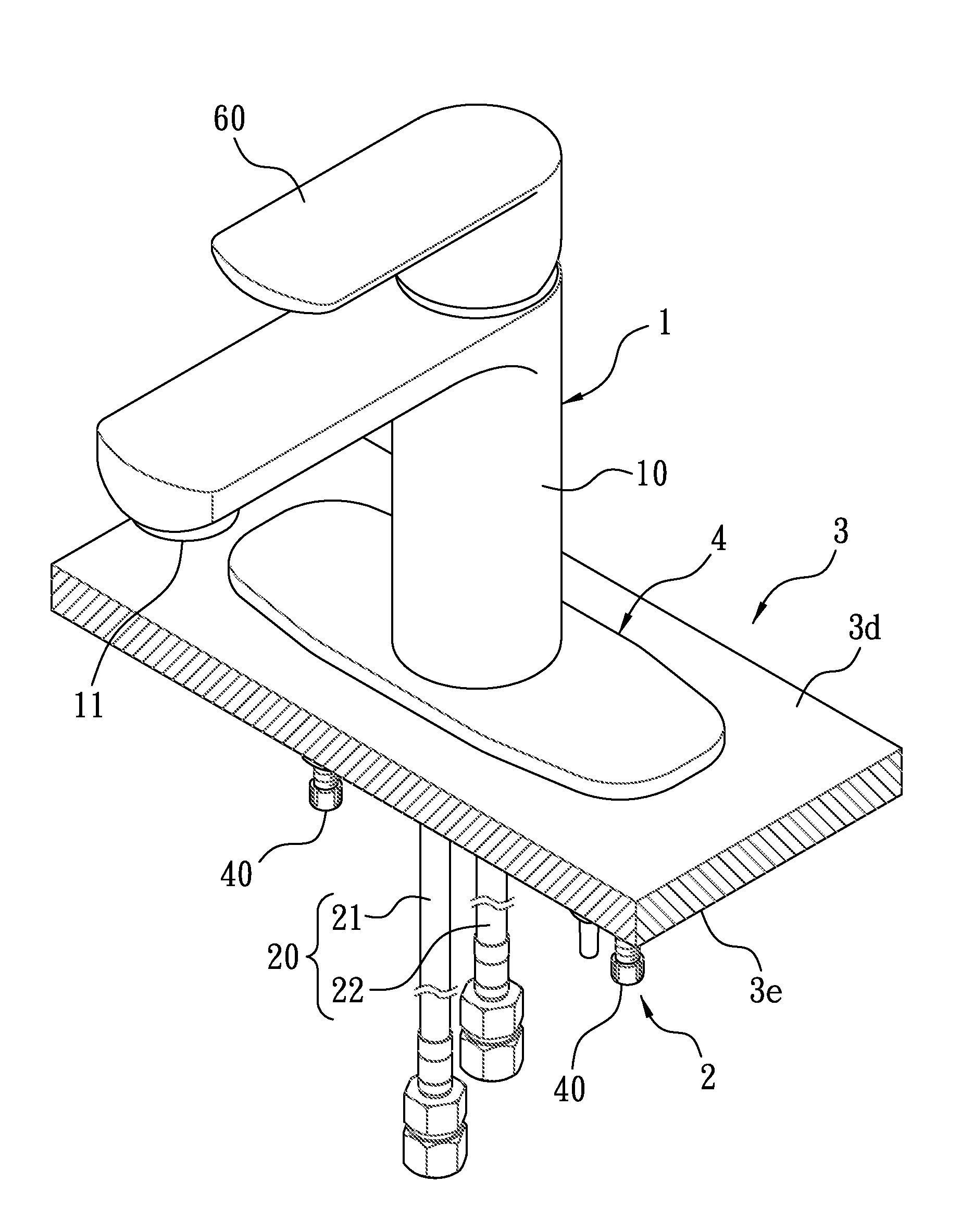
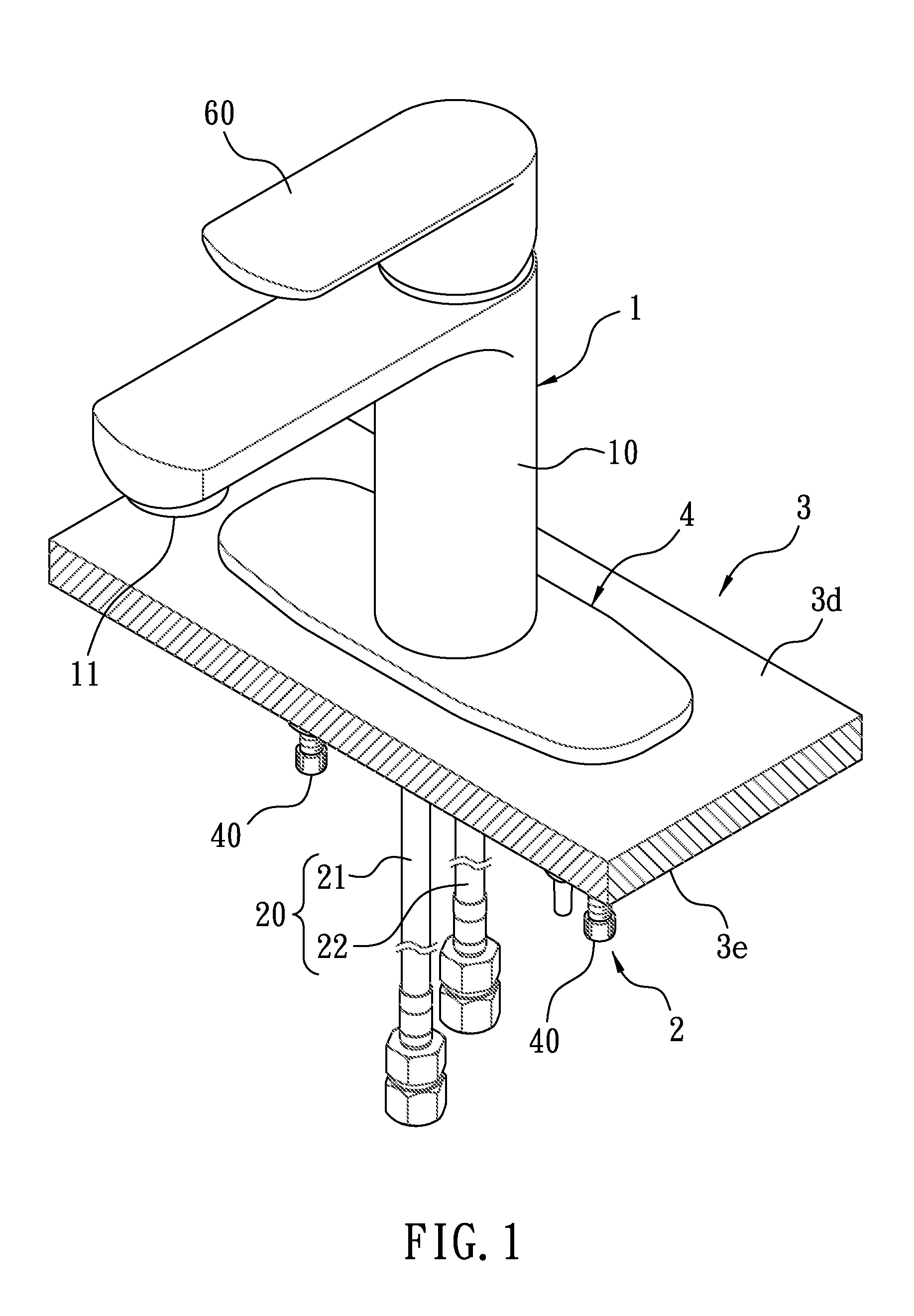
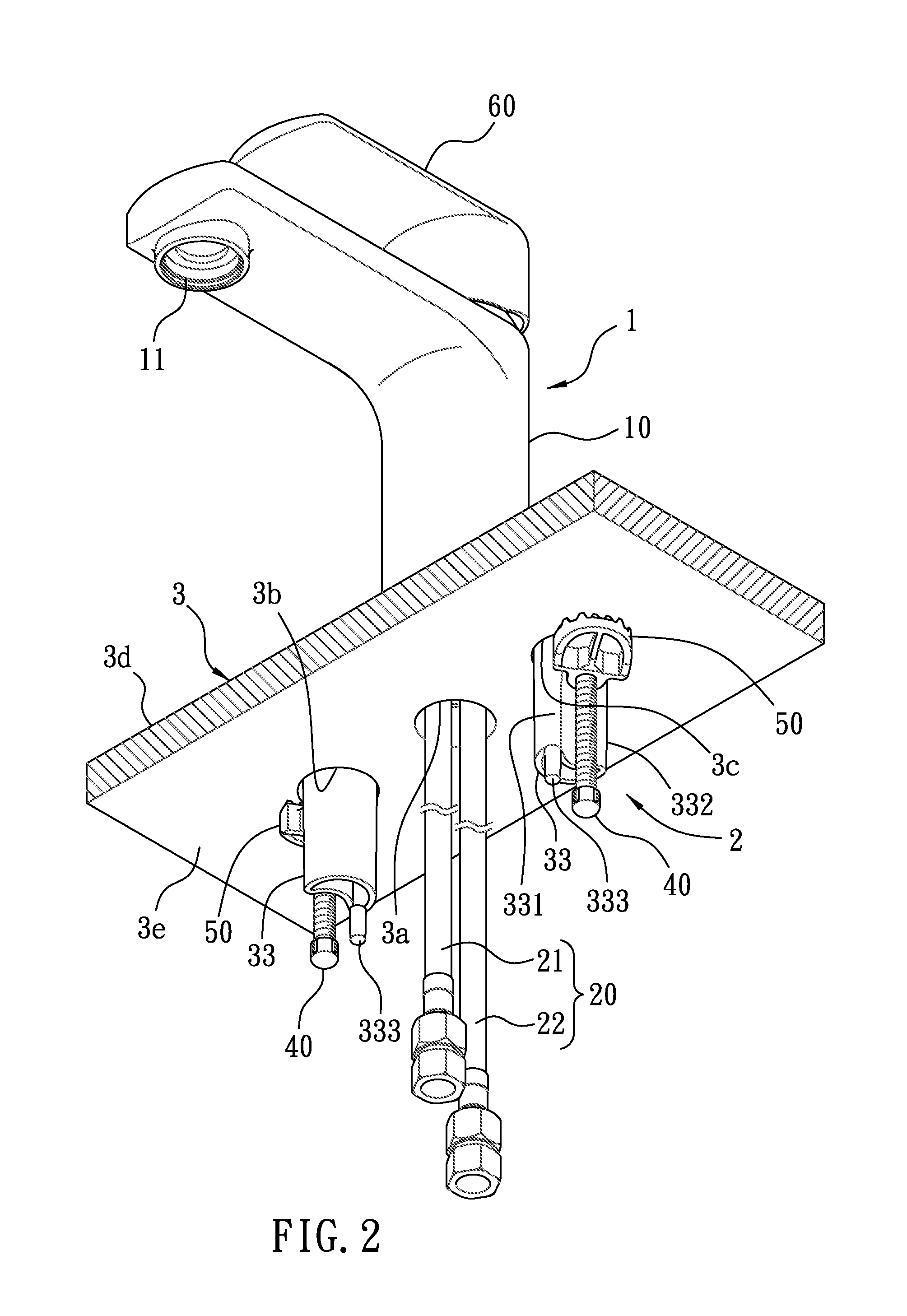
[0022]With reference to FIGS. 1-3, a lavatory faucet according to a preferred embodiment of the present invention is fixed on a basin 3 and comprises: a body 1 and a fixing device 2; the body 1 includes a housing 10 and a supply pipe assembly 20 connecting with the body 10 to delivery water; the fixing device 2 includes a mounting seat 30, two screw rods 40, and two clamping blocks 50; the basin 3 includes a central orifice 3a, a left orifice 3b, and a right orifice 3c, wherein a diameter of each of the central orifice 3a, the left orifice 3b, and the right orifice 3c is less than 32 mm.

[0023]An improvement of the lavatory faucet of the present invention is described as follows.

[0024]The mounting seat 30, as shown in FIGS. 4 and 5, includes an upper fitting sleeve 31, two extending wings 32 extending outwardly from a bottom end of an outer wall of the upper fitting sleeve 31 to abut against a top face 3d of the basin 3, and two support feet 33 extending downwardly from two bottom en...


PUM


Abstract

A lavatory faucet is fixed on a basin and contains: a body and a fixing device. The body includes a housing and a supply pipe assembly; the fixing device includes a mounting seat, two screw rods, and two clamping blocks; the basin includes a central orifice, a left orifice, and a right orifice. The mounting seat includes an upper fitting sleeve, two extending wings for abutting against a top face of the basin, and two support feet. The upper fitting sleeve has a channel defined therein relative to the central orifice, each extending wing has a through hole to insert each support foot, and each support foot has a first stopping fence. Each screw rod extends out of the through hole and is rotated above the mounting seat, each clamping block is screwed with each screw rod and is limited by the first stopping fence as rotating each screw rod.

Description

FIELD OF THE INVENTION[0001]The present invention relates to a lavatory faucet fixed on a basin with a central orifice, a left orifice, and a right orifice.BACKGROUND OF THE INVENTION[0002]A conventional facet is installed in a narrow space below a basin which is located in a kitchen or a bathroom.[0003]A positioning structure for a faucet disclosed in U.S. Pat. No. 8,763,175 B2 is fixed on the basin from an upper end of the basin. The faucet contains a body and a fixing device for installing the faucet on the basin from the upper end of the basin. The fixing device includes a mounting seat, two screw rods, and two clamping blocks. The mounting seat is inserted into an orifice on the basin and is employed to fix the body and to insert a supply pipe assembly. The supply pipe assembly has a first inlet pipe for flowing cold water, a second inlet pipe for flowing hot water and an inflow pipe for flowing a mixed water of the cold water and the cold water. The two screw rods are rotated ...

Claims


Application Information

Patent Timeline
Patent Type & Authority Applications(United States)
IPC IPC(8): E03C1/04E03C1/02
CPCE03C1/021E03C1/0401E03C2001/0416
Inventor HSU, WEIMIENLIN, YIPINGYUAN, JAHUALI, CHUNHUNGTANG, XIAOMAO
Owner GLOBE UNION INDAL
Why Eureka
Try Eureka