

Electrophoretic device having a transparent light state
a technology of electrotrophoretic devices and light states, applied in liquid surface applicators, instruments, coatings, etc., can solve the problems of inability to achieve transparent state, etc., to achieve sufficient beam absorption and improve release flexibility
- Summary
- Abstract
- Description
- Claims
- Application Information
AI Technical Summary
Benefits of technology
Problems solved by technology
Method used
Image

Examples
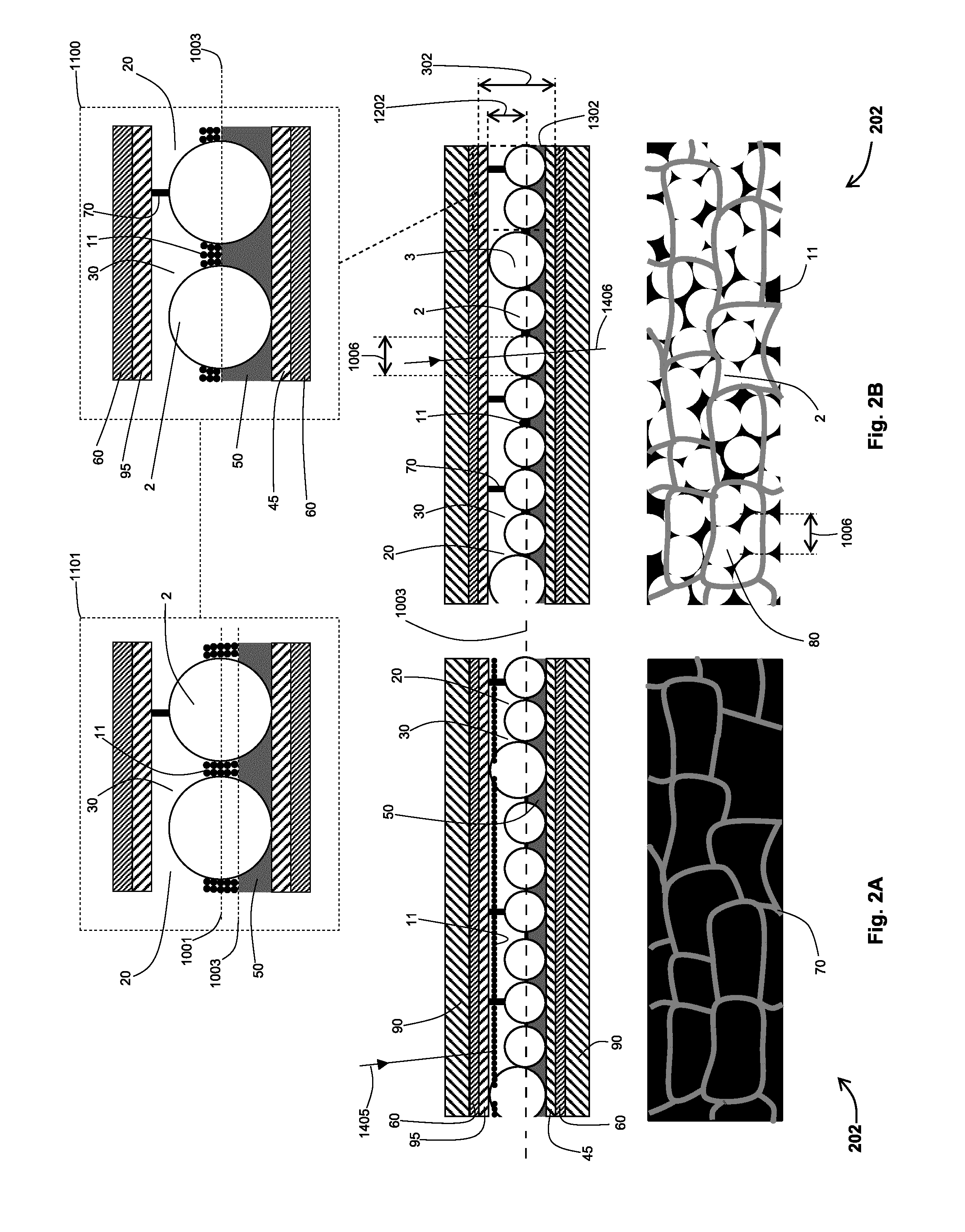
embodiment 202
[0255]In embodiments a light attenuator has an electrophoretic cell containing an electrophoretic ink in one or more volumes or cavities, the electrophoretic cell has particles of at least one charge polarity or type and has at least two extreme light states, in a first light state particles are spread within a cell to lie in the path of light through a cell (so that light is absorbed, attenuated, partially transmitted, reflected, or scattered) and in a second light state particles are concentrated within a cell to remove them significantly from the path of light through a cell (so that visible light is transmitted); to reach the second light state an electrophoretic cell uses a monolayer of closely packed protrusions to deflect particles in an electrical field away from their natural path (from a front electrode to a rear electrode) causing the particles to move over the surface of the solid protrusions and further causing particles to be driven to concentrate in the volume between...
embodiment 201
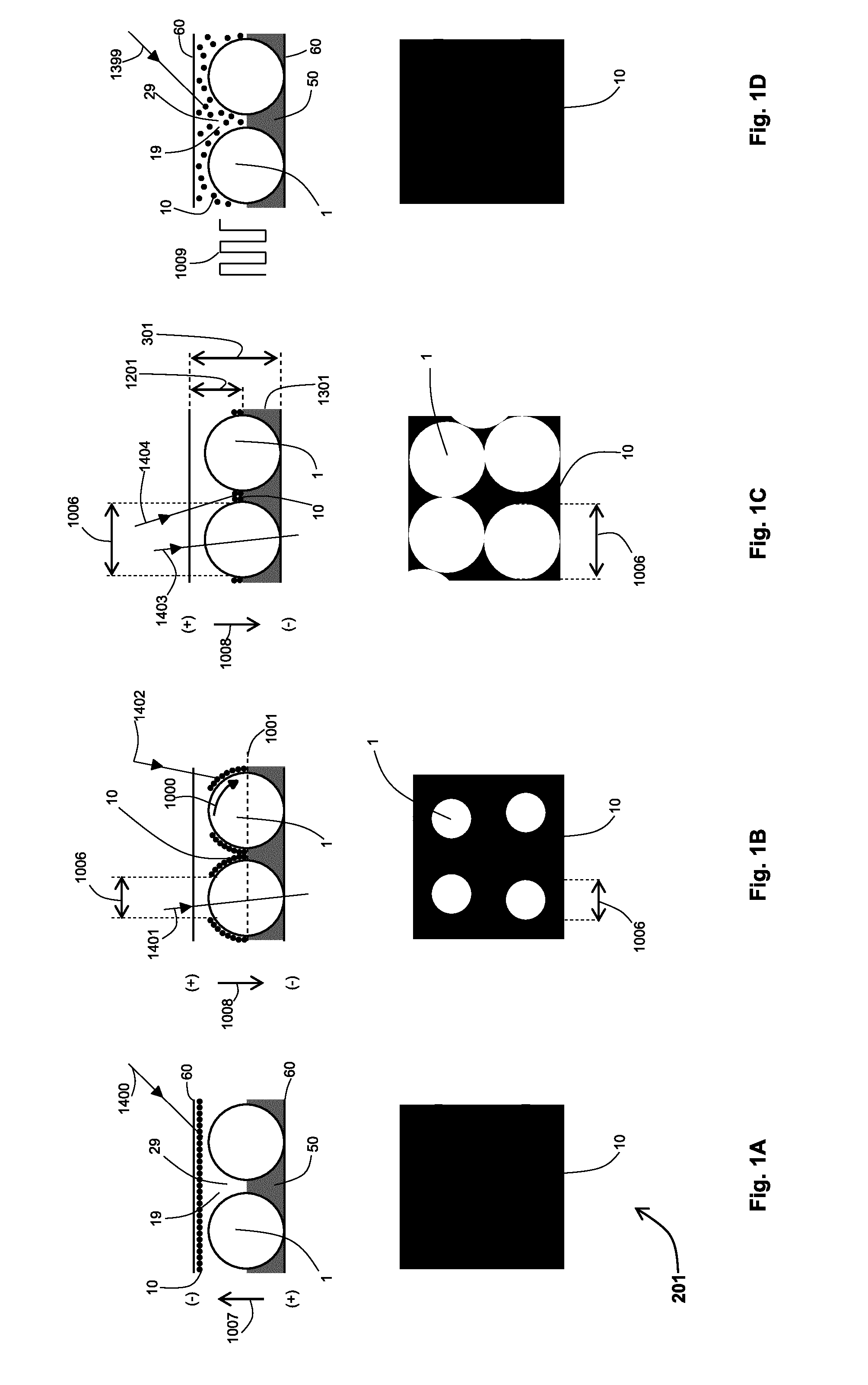
[0266]Visible light ray 1400 incident on electrophoretic cell 301 is absorbed by particles 10. Crucially, a uniform black, light absorbing first light state is readily available when the black particles typically used in electrophoretic ink displays are used in the current embodiments, these are discussed later. This high quality black, first light state of embodiment 201 contrasts with the lack of a black state in prior art light control devices.
[0267]The face view of FIG. 1A shows a uniform black (or dark) state because particles 10 are spread over a face of electrophoretic cell 301. Embodiment 201 has a black state that is opaque and provides a privacy function because the layer of particles 10 spread adjacent an electrode face is a stacked layer of particles whose diameters generally range from 100 nm to about 2 micron (the stacking is not shown in FIG. 1A). The thickness of the stacked layer of particles is determined by the particle loading (percentage) in an electrophoretic i...
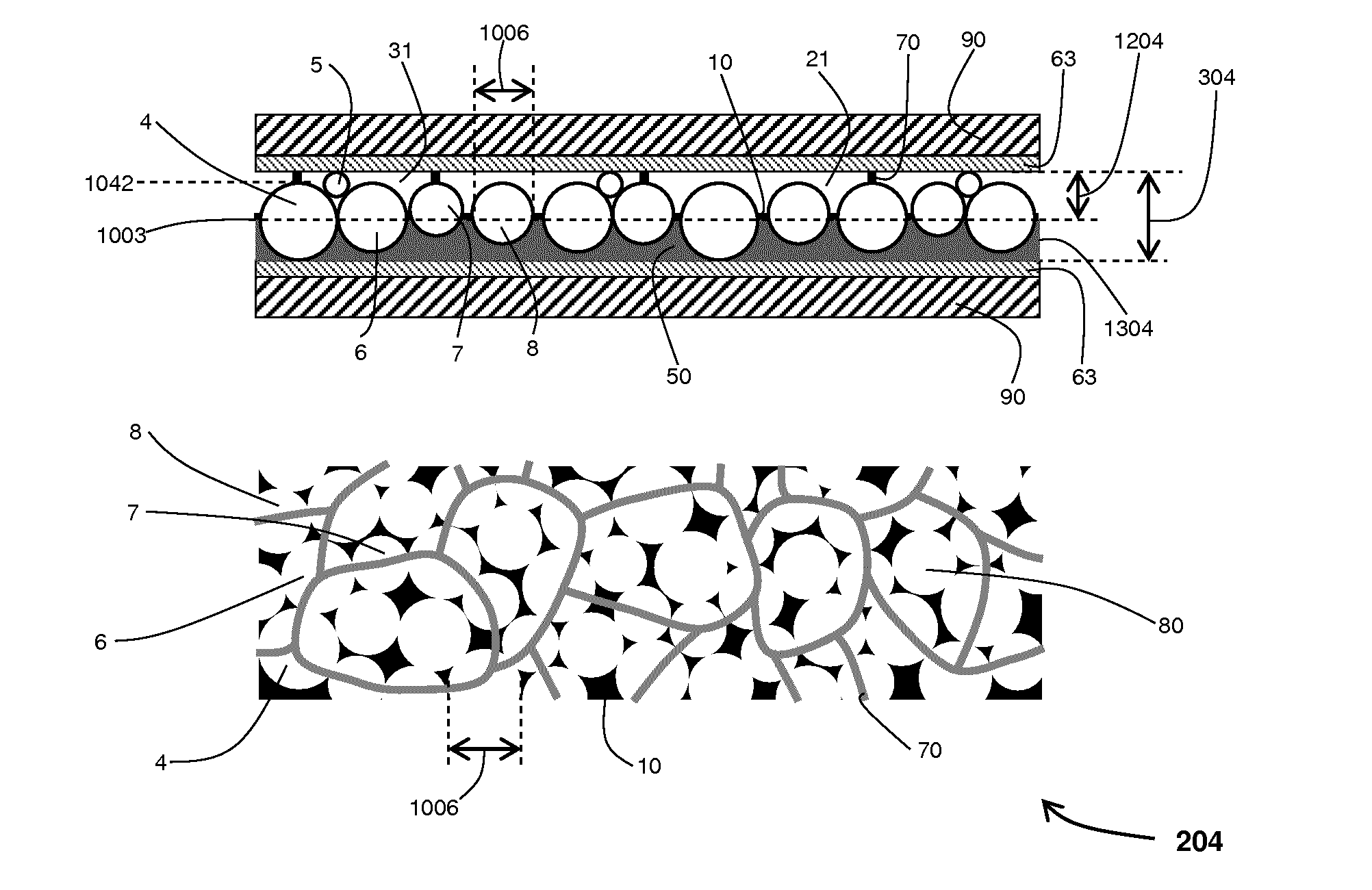
embodiment 204
[0318]Positively charged, black particles 10 are suspended in a suspending fluid 21 and their associated electrophoretic ink is 31. Similar to previous embodiments the layer occupied by an electrophoretic ink (31 in this case) is indicated by 1204, and the solid polymer structure within an electrophoretic cell 304 is indicated by 1304 and it includes the polymer balls 4, 6, 7 and 8 as well as space filling polymer 50. But in this embodiment the centres of the polymer balls do not lie on the same plane and polymer 50 is filled to a plane 1003 that approximates an equator plane or polymer 50 is filled up to or below a plane through the centre (in the z-axis) of the cell 304. In embodiment 204 the top and bottom electrodes 63 are silver nanowires but any transparent electrode is suitable.
[0319]Embodiment 204 is an example of where protrusions have a number of different sizes. In embodiments, a random close packing of polymer balls having a number of different diameters results in a hig...
PUM
| Property | Measurement | Unit |
|---|---|---|
| refractive index | aaaaa | aaaaa |
| reflectance | aaaaa | aaaaa |
| distance | aaaaa | aaaaa |
Abstract
Description
Claims
Application Information