
Trash Can Liner Box Support and Dispensing Arrangement

a technology for trash cans and liners, which is applied in the field of trash can liners and dispensing arrangements, to achieve the effects of easy movement of both arms, low peel adhesion, and low peel adhesion

Inactive Publication Date: 2018-02-15
ACKERMAN SYBIL
View PDF3 Cites 4 Cited by
  • Summary
  • Abstract
  • Description
  • Claims
  • Application Information

AI Technical Summary

Benefits of technology

The present invention relates to a holder for a trash container that can hold a box of trash can liners. The holder is placed inside the trash container and has a base that rests on the bottom of the container. The holder has four pivotable arms that can hold the trash can liners in the bottom of the container. The holder can be easily attached to the container using adhesive or mechanical fasteners. The trash can liners are adhered to the bottom of the container or directly to the bottom wall of the container. The bottom of the container has openings to allow the trash can liners to be easily removed. The invention provides a convenient and efficient way to use trash can liners in a trash container.

Problems solved by technology

Since the location where such disposable trash can liners are to be stored may be. very inconvenient with respect to where the trash can was actually deployed, certain inventions offered basic storage and dispensing capabilities for the trash can liners.

Method used


Image

  • Trash Can Liner Box Support and Dispensing Arrangement
  • Trash Can Liner Box Support and Dispensing Arrangement
  • Trash Can Liner Box Support and Dispensing Arrangement

Examples


first embodiment

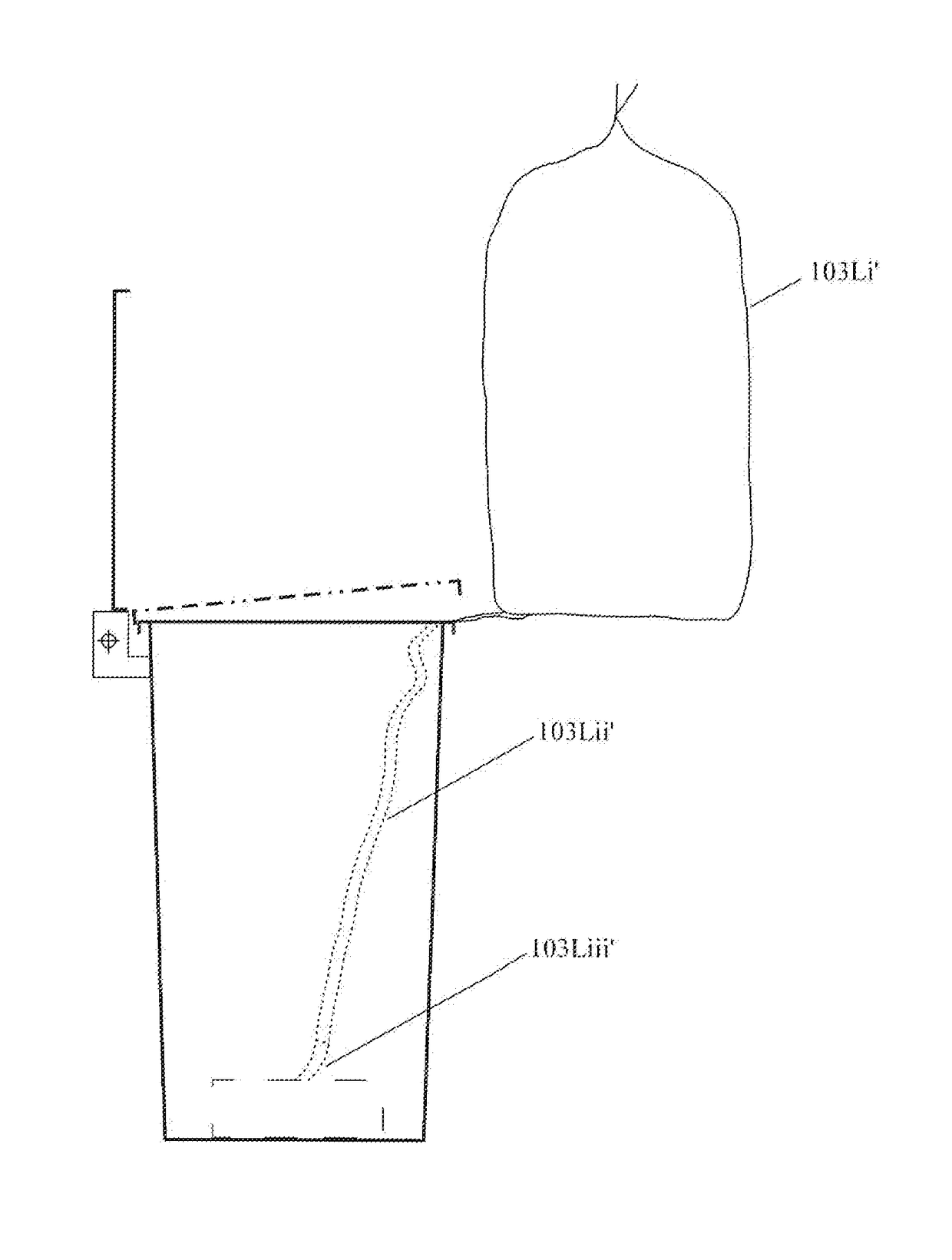
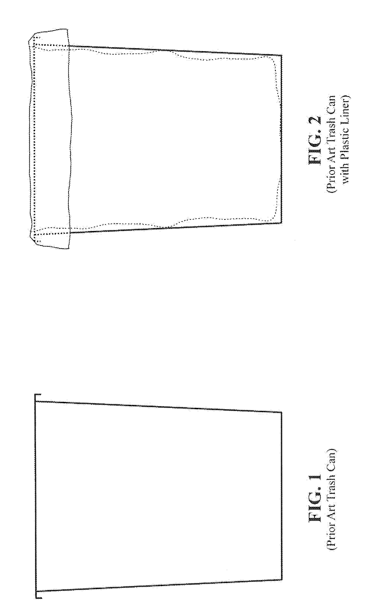
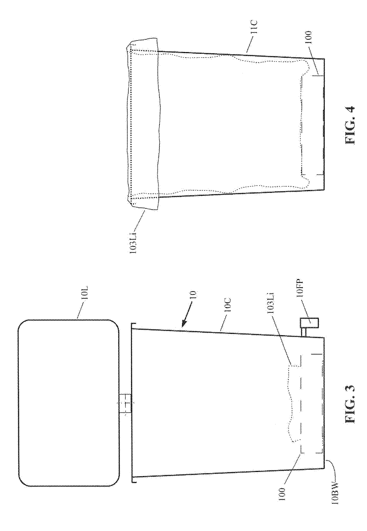
[0048]Secured to the bottom wall 10BW of the can 10C is a box assembly with trash can liners 100. The box 100, although shown secured to the bottom of the can 10C of trash can assembly 10, may similarly be secured to the bottom of any other trash can known in the art, including, but not limited to, the prior art trash can without a lid, as illustrated in FIG. 1. FIG. 4 illustrates a prior art trash can 11C formed without a pivotal lid, and which trash can is shown with the first trash can liner 103Li having been withdrawn from the box assembly 100 and expanded to fill the trash can, and to overhang the lip of the trash can,

[0049]FIGS. 5-7B show enlarged front, cross-sectional, and top and bottom views, respectively, of the box assembly 100 with trash can liners therein (e.g., 103Li, 103Lii, 103Lii, etc.). The box assembly 100 may contain trash can liners that may be particularly joined and successively packed therein (see e.g., FIG. 6), which is discussed further hereinafter.

[0050]T...

embodiment 310

[0063]FIGS. 17-18 show side and front views of a trash can embodiment 310, which may also be formed with or without the conventional lid and associated lid actuation mechanism and foot pedal.

[0064]The trash can 310 may be formed with a conventional upstanding wall and bottom wall 312 to form a container, and may additionally be formed with a floor wall 311 that may be positioned at a height above the bottom wall to form a lower chamber being sufficiently large to accommodate a box 301 of trash can liners to be received therein. An opening 313 may be formed in one side of the upstanding wall of the trash can, being sufficiently sized with respect to the profile of the box of liners 301, to permit ingress and egress of the box from beneath the floor 311. The floor 311 may have, as seen in FIG. 19, an opening 314 formed therein, through which the interconnected liners may be pulled into the container portion of the trash can. In one embodiment, the opening 314 may begin proximate to a ...


PUM


Abstract

Trash can embodiments dispense plastic liners. First, a holder secured to a bottom wall of a trash container includes a base, and four posts, each having a corresponding pivotable arm biased from a retracted position into an extended position. The arms are pivotally coupled to respective posts to releasably retain a box of liners therein, as liners are withdrawn from the box. Second, a particularly formed trash container includes a floor wall positioned above the bottom wall to divide the container into lower and upper chambers. The side wall has a first opening interconnected with the lower chamber, and a second opening interconnected, with the second opening and the lower and upper chamber. The floor wall has an opening interconnected with the second side wall opening. The first side wall opening provides clearance for the box. The second opening, provides clearance for a first liner protruding from the box.

Description

CROSS REFERENCES TO RELATED APPLICATIONS[0001]This application claims priority on U.S. Provisional Application Ser. No. 62 / 373,382, filed on Aug. 11, 2016, the disclosures of which are incorporated herein by reference.FIELD OF THE INVENTION[0002]The present invention relates to the use of plastic liners in a trash can, and more particularly to apparatus configured for use in supporting a box of plastic liners within a trash can, for dispensing and use of the liners therefrom.BACKGROUND OF THE INVENTION[0003]A centralized system for community trash collection and disposal began in England around 1875, and was similarly utilized in the U.S. shortly thereafter. The system necessitated the use of a garbage bin, receptacle, trash can, etc., to temporarily store refuse, until it would to be collected. There are a number of early patents to improved trash / garbage cans (e.g., U.S. Pat. No. 1,218,632 to Derry).[0004]Some of the early trash can-related patents include the use of a liner. For ...

Claims


Application Information

Patent Timeline
Patent Type & Authority Applications(United States)
IPC IPC(8): B65F1/06B65F1/14B65B67/12
CPCB65F1/062B65F1/068B65B67/1266B65F1/1421B65F1/163
Inventor ACKERMAN, SYBIL
Owner ACKERMAN SYBIL
Learn More