Liner for Prosthetic Limb

a prosthetic limb and liner technology, applied in the field of liner for upper and lower limb prosthesis, can solve the problems of limited liner elasticity, inability to reverse, and buildup of perspiration, and achieve the effect of convenient donned

Inactive Publication Date: 2016-02-04
UNIVERSITI MALAYA
View PDF1 Cites 9 Cited by
  • Summary
  • Abstract
  • Description
  • Claims
  • Application Information

AI Technical Summary

Benefits of technology

[0009]It is an objective of the present invention to prov

Problems solved by technology

Perspiration control is a major issue with existing prosthetics and liners as the prior arts are usually airtight, which has several disadvantages.
However, the elasticity of the liner is limited and it is not reversi

Method used


Image

  • Liner for Prosthetic Limb
  • Liner for Prosthetic Limb
  • Liner for Prosthetic Limb

Examples


examples

[0025]Below is an example of a method for preparing the liner for limb prosthesis from which the advantages of the present invention may be more readily understood. It is to be understood that the following example is for illustrative purpose only and should not be construed to limit the present invention in any way.

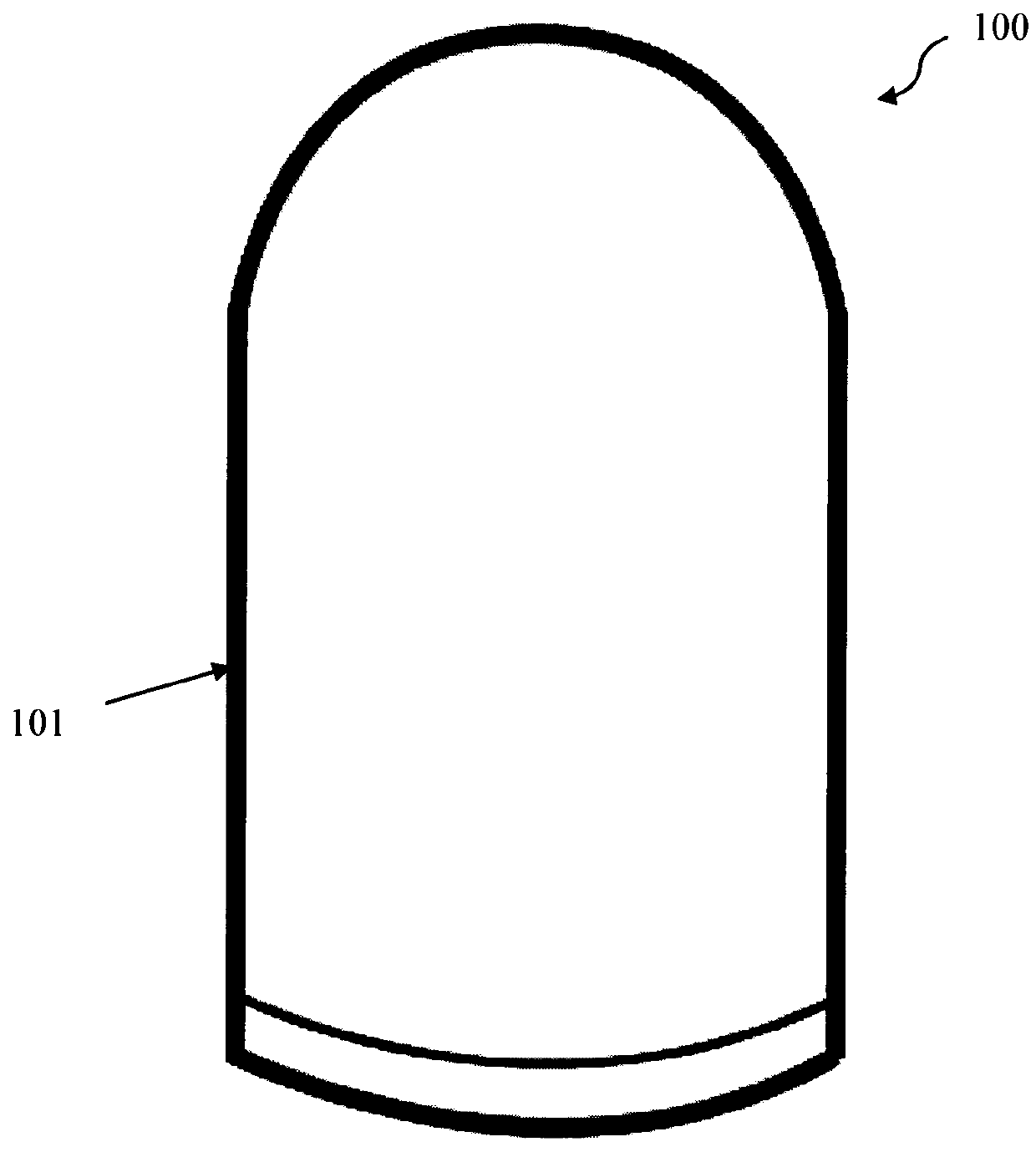
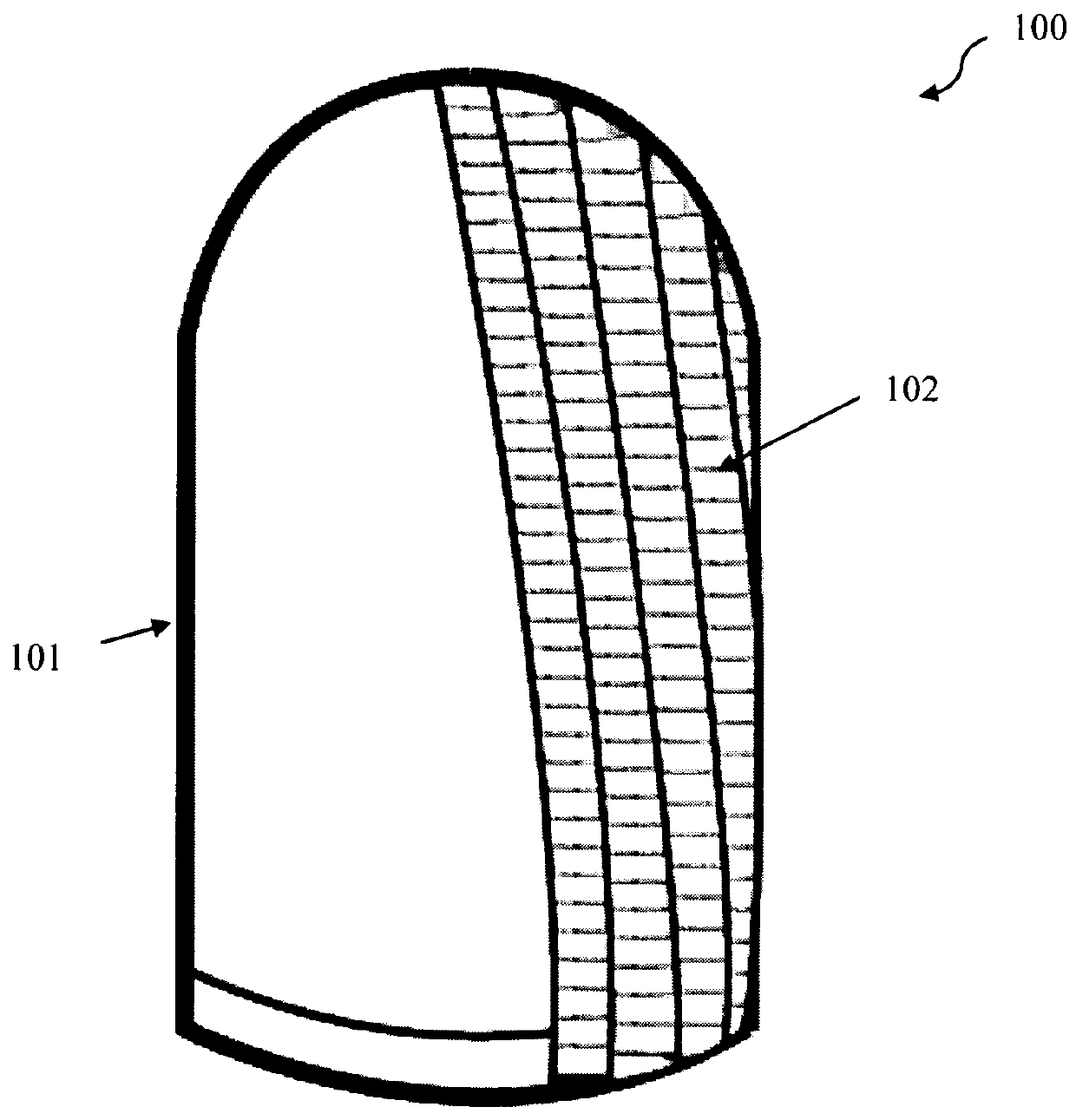
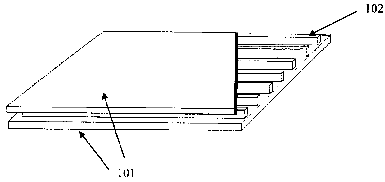
[0026]A positive cast of an amputee's residual limb is prepared. A layer of elastic fabric (101), preferably made from nylon, wool or cotton, is placed over the positive cast of the residual limb (FIG. 1). Next, a layer of foam (102) (example, neoprene) is laid over the first layer of elastic fabric. The layer of foam (102) is cut into uniform strips (FIG. 2). This allows the liner (100) to be both elastic and flexible. Another layer of elastic fabric (101) is then placed over the layer of foam (102) (FIG. 3). The three layers comprising the foam strips (102) and elastic fabrics (101) are then sewn together using a sewing machine to form a unitary prosthetic limb liner (...


PUM


Abstract

The present invention relates to a liner for limb prosthesis (100), characterized by a foam layer (102) comprising a plurality of strips of foam (102) and a plurality of elastic fabric layers (101), wherein the foam layer (102) is sandwiched between the elastic fabric layers (101) wherein the liner for limb prosthesis (100) comprises a cylindrical or cone shape, with an open end and one close end.

Description

BACKGROUND OF THE INVENTION[0001]1. Field of the Invention[0002]This invention relates to a liner for upper and lower limb prosthesis using elastic fabric and foam.[0003]2. Description of Related Arts[0004]Prosthesis liner is used for comfort as well as coupling the prosthetic devices to the residual limb for amputees. The interface between the residual limb and the prosthesis is essential for fit and comfort. Perspiration control is a major issue with existing prosthetics and liners as the prior arts are usually airtight, which has several disadvantages.[0005]For example, U.S. Pat. No. 6,136,039 disclosed an invention for a dual durometer silicone liner for prosthesis that has a inner silicone elastomer layer and a relatively harder outer silicone elastomer layer. The liner is formed of a closed end, air tight inner layer of silicone rubber that is highly compliant. However, the elasticity of the liner is limited and it is not reversible.[0006]Furthermore, in U.S. Pat. No. 5,658,35...

Claims


Application Information

Patent Timeline
IPC IPC(8): A61F2/78
CPCA61F2/7812A61F2230/0069A61F2002/7818A61F2002/7837A61F2002/785A61F2230/0067
Inventor ABU OSMAN, NOOR AZUANGHOLIZADEH, HOSSEIN
Owner UNIVERSITI MALAYA
Why Eureka
Try Eureka