
Gas turbine engine exhaust ejector/mixer

a technology of exhaust ejector and mixer, which is applied in the direction of machines/engines, valve construction, transportation and packaging, etc., can solve the problems of vibration and negative consequences for surrounding hardware of exhaust ejector/mixer

Active Publication Date: 2016-02-04
PRATT & WHITNEY CANADA CORP
View PDF8 Cites 3 Cited by
  • Summary
  • Abstract
  • Description
  • Claims
  • Application Information

AI Technical Summary

Benefits of technology

The patent describes an exhaust ejector / mixer for a gas turbine engine that helps improve engine performance. The exhaust ejector / mixer is located at the exhaust end of the engine and includes an annular wall with a plurality of circumferentially distributed lobes and a support member that interconnects at least some of the lobes. The lobes are formed with a trough and a convex bight that creates a joint surface. The support member has corresponding concave joint surfaces that match up with the mating convex joint surfaces of the lobes. This design helps to optimize engine performance by promoting better airflow and mixing of air along the main gas path. Additionally, the exhaust ejector / mixer can be adapted for different engine configurations, such as turbofan or turbo-shaft engines, by adjusting the number and positioning of the lobes.

Problems solved by technology

In addition, exhaust ejector / mixers may be prone to vibrations, which has negative consequences for the surrounding hardware.

Method used


Image

  • Gas turbine engine exhaust ejector/mixer
  • Gas turbine engine exhaust ejector/mixer
  • Gas turbine engine exhaust ejector/mixer

Examples


Embodiment Construction

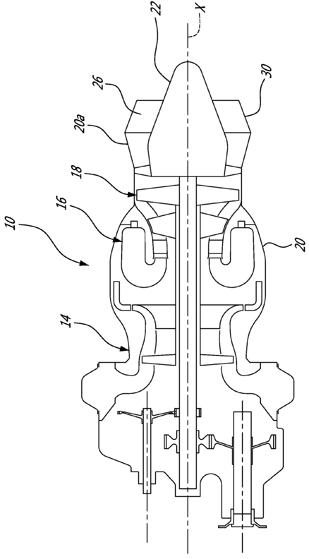
[0015]FIG. 1 illustrates a turbo-shaft gas turbine engine 10 of a type preferably provided for use in subsonic flight, generally comprising in serial flow communication a compressor section 14 for pressurizing the air, a combustor 16 in which the compressed air is mixed with fuel and ignited for generating an annular stream of hot combustion gases, and a turbine section 18 for extracting energy from the combustion gases. The gas turbine engine 10 includes a core engine casing 20 which encloses the turbo machinery of the engine. The main air flow passes through the core of the engine via a main gas path 26, which is circumscribed by the core engine casing 20 and allows the flow to circulate through the multistage compressor 14, combustor 16 and turbine section 18 as described above.

[0016]At the aft end of the engine 10, an exhaust cone 22 is centered about a longitudinal axis X of the engine 10, the exhaust cone 22 being connected to an aft end of the turbine section 18. The exhaust ...


PUM


Abstract

An ejector / mixer for a gas turbine engine includes an annular wall having upstream end adapted to be fastened to an engine case and a downstream end forming a plurality of lobes. A support member interconnects the lobes, and includes an annular blade located radially inwardly of the bight of the lobes. The lobes extend radially inwardly downstream relative to the annular wall and the support member includes an annular blade and has spaced apart joint surfaces spaced apart to coincide with the joint surfaces of a respective lobes. The spaced-apart joint surfaces of the support member being profiled to mate with the corresponding joint surface of the lobes.

Description

TECHNICAL FIELD[0001]The application relates generally to aircraft gas turbine engines and, more particularly, to aft section of the engine including an ejector mixer.BACKGROUND OF THE ART[0002]In gas turbine engines, hot high velocity air exits from the turbine through the core gas path. The exhaust gases may be constrained by an exhaust case section in the form of a corrugated annular case extension having ejector / mixer lobes. Turbofan engines generally use exhaust mixers in order to increase the mixing of the high and low velocity exhaust gas flows. Turbo-shaft engines may be provided with similar devices sometimes referred to as ejectors. Exhaust mixers / ejectors may experience thermal variation and / or radial deflection due to exposure to the high and low velocity flows. In addition, exhaust ejector / mixers may be prone to vibrations, which has negative consequences for the surrounding hardware. As such, it is generally desirable to increase the stiffness or rigidity of the exhaus...

Claims


Application Information

Patent Timeline
IPC IPC(8): F02K1/38F02C7/18
CPCF02C7/18F02K1/386
Inventor DI PAOLA, FRANCOLEFEBVRE, GUYL'ESPERANCE, PATRICKEMARD-PARENT, GABRIEL
Owner PRATT & WHITNEY CANADA CORP
Features
  • Generate Ideas
  • Intellectual Property
  • Life Sciences
  • Materials
  • Tech Scout
  • Unparalleled Data Quality
  • Higher Quality Content
  • 60% Fewer Hallucinations
Learn More