Wind Turbine Blade Lowering Apparatus

Active Publication Date: 2016-02-11
HEAVYELEVATOR IP LLC
View PDF7 Cites 23 Cited by
  • Summary
  • Abstract
  • Description
  • Claims
  • Application Information

AI Technical Summary

Benefits of technology

[0011]The present invention relates to a wind turbine enabling a

Problems solved by technology

The cost of lowering and lifting rotor blades to the top of tall land based towers for servicing can be prohibitive, mainly due to the reach of conventional cranes, which require much higher crane capacity than the actual weight being lifted.
This is due to the bending moment resulting from the reach of conventional cranes.
This adds a substantial cost for repair and blade

Method used


Image

  • Wind Turbine Blade Lowering Apparatus
  • Wind Turbine Blade Lowering Apparatus
  • Wind Turbine Blade Lowering Apparatus

Examples


Embodiment Construction

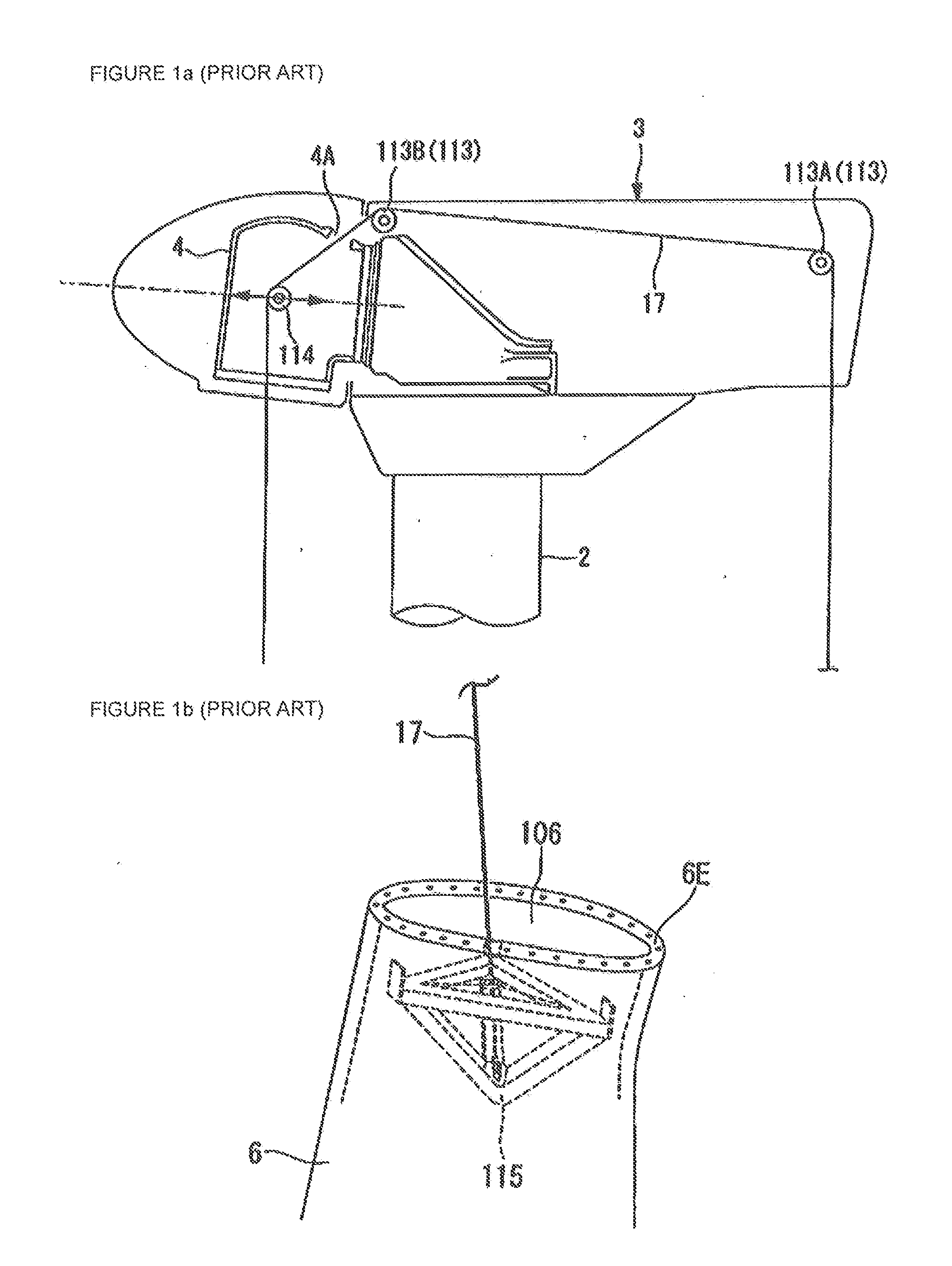
[0036]Refer to FIGS. 1a and 1b, which are side elevation views of part of a wind power installation of the prior art Pub. No.: WO / 2008 / 155976 International Application No.: PCT / JP2008 / 059474 published Dec. 24, 2008 of Tomohiro Umajiri, et al. “Suspension Device For Wind Wheel Blade, Method Of Mounting Wind Wheel Blade, And Method Of Constructing Wind-Driven Generator”. This publication discloses a suspension device for a wind turbine rotor blade including a method of mounting the blade, which allows the blade to be mounted and removed without using multiple construction machines.

[0037]The suspension device has a pulley (114), a holding section (115), and a winch. The pulley (114) leads a suspension wire (17) from the rotor head (4), on which the blade (6) is to be mounted, to the holding section (115) fixed inside the blade (6) at the root end or mounting end of the blade. The wire (17) is placed so as to be movable in the direction of the axis of rotation of the rotor head (4). The...


PUM

PropertyMeasurementUnit
Flexibilityaaaaaaaaaa

Abstract

The present invention relates to a wind turbine enabling a cost effective and easy attachment/replacement of rotor blades and to a method of attaching a rotor blade to a hub of a wind turbine. The wind turbine in accordance with the invention comprises a tower resting on a base, at least one rotor blade having a blade connector portion, a nacelle housing a shaft to which a hub is attached, the nacelle being mounted atop the tower. Said hub of the wind turbine comprises a plurality of hub connection flanges, each hub connection flange being adapted to be detachably connected to a blade connector portion of a rotor blade.

Description

BACKGROUND OF THE INVENTION[0001]1. Field of the Invention[0002]This invention relates to wind turbines housed in a nacelle atop a tall tower, and more particularly to an apparatus and method for raising or lowering a rotor blade of a wind power installation for connection to a hub or disconnection from the hub.[0003]2. Description of the prior Art[0004]The average wind turbine size is now approximately 1.5 MW with rotor diameters ranging from 70 to 85 m. This class of turbines has on average a nacelle weight of 50 tons (generators, gear box and nacelle housing) and a rotor weight of approximately 75 tons. To improve the economics of wind turbines, manufacturers have been designing taller towers to take advantage of greater wind energy at higher levels above ground. Manufacturers are increasingly relying on 80 and 100 m tower designs, rather than the shorter towers used previously. The cost of lowering and lifting rotor blades to the top of tall land based towers for servicing can b...

Claims


Application Information

Patent Timeline
IPC IPC(8): F03D1/00B66C23/18F03D1/06
CPCF03D1/001B66C23/185F03D1/0658B66C1/108B66C23/207F05B2240/916Y02E10/728F03D13/10Y02E10/72
Inventor SMITH, NEILKISSINGE, JOSHKILS, OLE
Owner HEAVYELEVATOR IP LLC
Why Eureka
Try Eureka