Sealable Terminal for Rechargeable Battery

a rechargeable battery and terminal technology, applied in the direction of batteries, sustainable manufacturing/processing, cell components, etc., can solve the problem of clear limit of the material of the battery cover to the lower section of the terminal, and achieve the effect of improving mechanical stability, improving sealing, and low friction

Active Publication Date: 2016-02-11
WEGMANN AUTOMOTIVE GMBH & CO KG
View PDF0 Cites 9 Cited by
  • Summary
  • Abstract
  • Description
  • Claims
  • Application Information

AI Technical Summary

Benefits of technology

[0008]The embodiments are based on the object of providing a terminal for a battery, which provides an improved sealing and an improved mechanical stability. Furthermore, the terminal should allow easy assembly of the battery and therefore inserting of the terminal post into the terminal during assembly with a low friction. The process of manufacturing the terminal and the process of injection molding a battery cover should be simplified and should be made more precise and reliable.
[0010]The concave lower section of the inner wall provides space for plastic material of the battery cover. While battery terminals as known in the prior art are only held by their outer walls within the battery cover, this embodiment of a terminal is completely embedded into the material of the battery cover in its mounting section, including the outer wall and the inner wall of the terminal. This gives enhanced stability to the battery terminal and results in a significantly higher retention force. This is not comparable to thin sliding elements. In contrast thereto, there is space for a significant layer of the battery cover's material covering the inner wall of the terminal's mounting section. The thickness of the battery cover's material may be 1 mm or more, preferably 3 mm. For molding a terminal into a battery cover, a pin of a molding tool is inserted into the terminal to limit the flow of the battery cover's material within the terminal. A circular edge at the inner wall of the terminal between the upper section and the lower section is in contact with the pin of the molding tool and ensures sealing of the area into which the battery cover's material can flow. This results in a clear limit of the battery cover's material to the lower section of the terminal.
[0011]The circular edge preferably is pressed against the pin of the molding tool. To obtain a secure sealing, the pin of the molding tool must at least closely fit into the diameter of the circular edge. The pin of the molding tool may also be pressed into the terminal, extending the inner diameter of the circular edge slightly. Therefore it is preferred, if the circular edge is opposed to the protrusion at the outer wall of the terminal, as this protrusion acts as a reinforcement and allows absorbing of comparatively high forces without deformation of the terminal.
[0012]In a further embodiment, the mounting section has a decreasing material thickness starting from the torque ring to the end of the mounting section. As the possible holding forces decrease towards the end of the mounting section due to the anchoring forces of the labyrinth rings, the thickness of the walls can be reduced, thus saving further material and mass.

Problems solved by technology

This results in a clear limit of the battery cover's material to the lower section of the terminal.

Method used


Image

  • Sealable Terminal for Rechargeable Battery
  • Sealable Terminal for Rechargeable Battery
  • Sealable Terminal for Rechargeable Battery

Examples


first embodiment

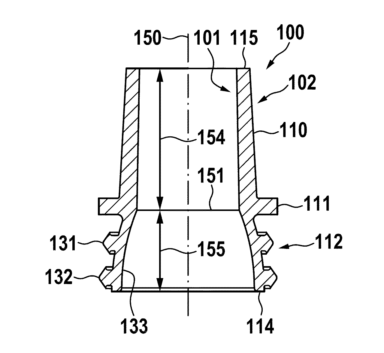
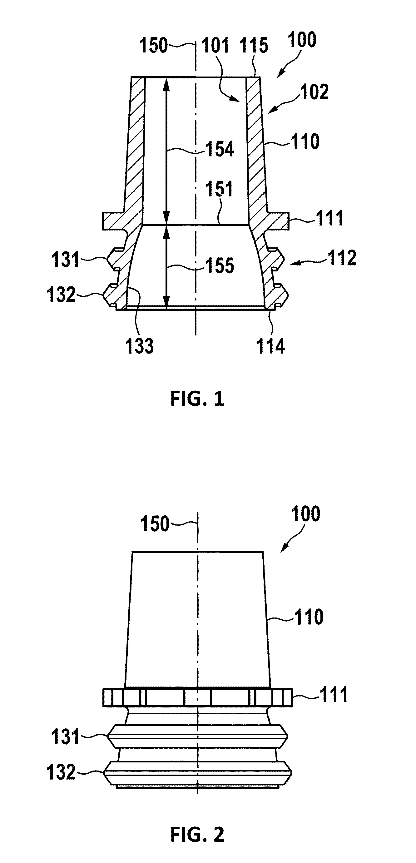
[0030]In FIG. 2, a side view of a first embodiment is shown.

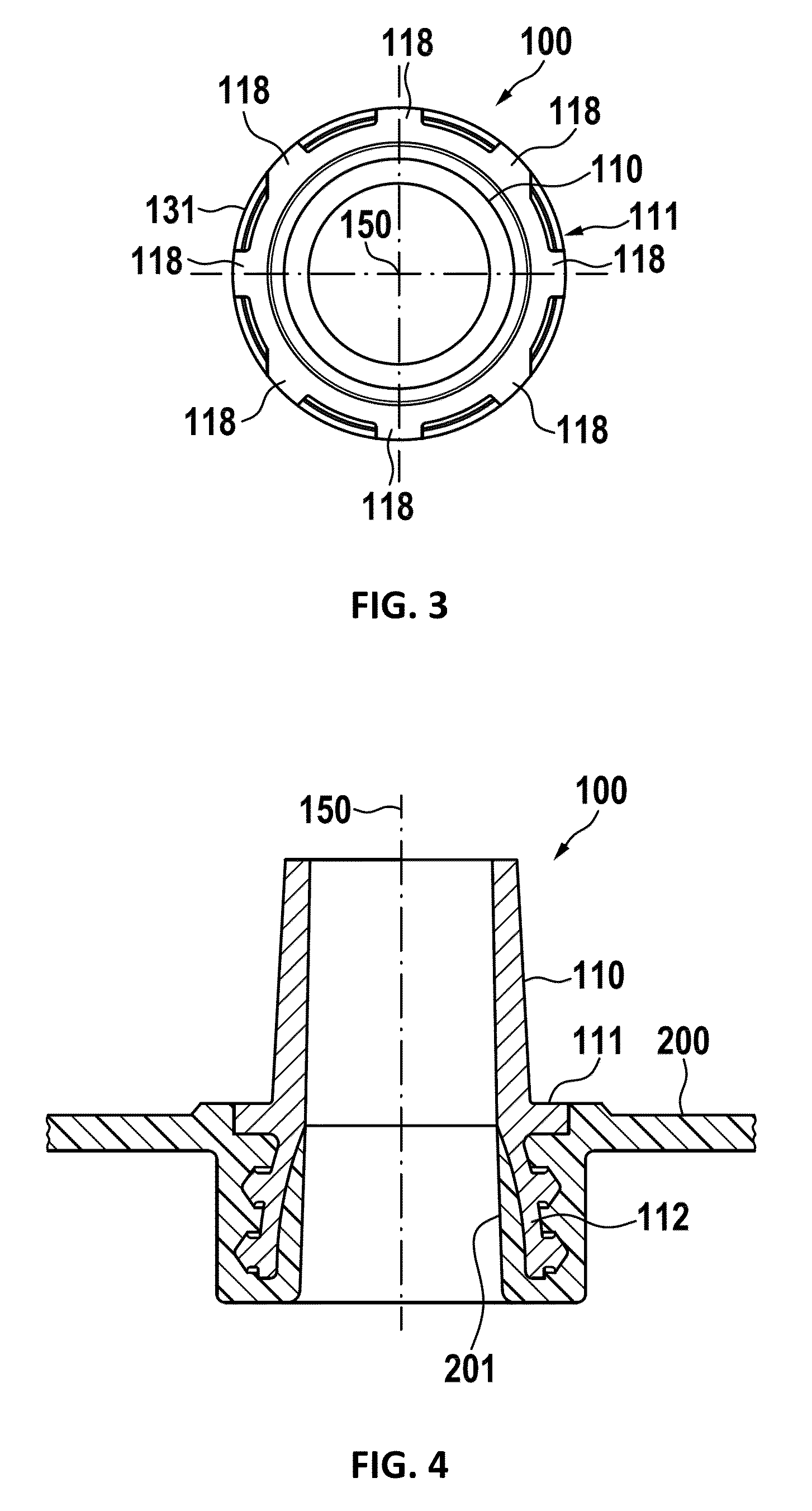
[0031]In FIG. 3, a top view of a first embodiment is shown. Here, protrusions 118 of the torque ring 111 are shown.

[0032]In FIG. 4, a sectional view of a terminal embedded into a battery cover 200 is shown. Here, the mounting section 112 of the terminal 100 is completely embedded into the battery cover material, including the outer wall and the inner wall. This improves sliding of a terminal post into the terminal during assembly, and further increases mechanical stability, as the battery cover material better supports the terminal mounting section 112.

[0033]In FIG. 5, an embodiment with an inserted molding tool post is shown. This may be a stage during injection molding of the battery cover 200. To prevent flow of the battery cover material into the upper section of the terminal, a pin of a molding tool 300 is inserted into the terminal. The tool preferably has a conical shape and a size, such that it exactly fits to the d...

second embodiment

[0035]In FIG. 7, a terminal is shown. Here, instead of the circular edge, there is a step 152. This step is also suitable for sealing the terminal against the pin of the molding tool 300. It further allows a precise measurement of the length of the lower section 155.

[0036]In FIG. 8, a further embodiment is shown. Here, the mounting section 112 has a slightly modified labyrinth. Instead of having straight planes between the labyrinth rings 131, 132, there are protrusions 140 and 141 having an arch-shaped cross-section. Such arch-shaped cross-sections reduce the mechanical tensions in the material of the terminal and of the battery cover, thus increasing mechanical stability and lifetime.

[0037]In FIG. 9, a sectional view of an embodiment of the terminal is shown. Here again, the pin of the molding tool is inserted for demonstration purposes. Due to the complete enclosure of the mounting section 112 by the material of the battery cover 200, the thickness of the walls can be decreased. ...


PUM

PropertyMeasurementUnit
thicknessaaaaaaaaaa
thicknessaaaaaaaaaa
diameteraaaaaaaaaa

Abstract

A terminal for a battery has a mounting section and a contacting section. There is a torque ring between the mounting section and the contacting section. The mounting section is for holding the terminal within a battery cover, into which it preferably is injection molded. The terminal is a hollow body, which has an outer surface and an inner surface. At the contacting section, the outer surface is conically shaped. At the mounting section, the outer surface has at least one labyrinth ring forming a labyrinth. The inner surface comprises at least two sections. An upper section is essentially surrounded by the contacting section, and preferably has a conical shape. A lower section is essentially surrounded by the mounting section. The lower section preferably has a concave cross-sectional shape. Between the upper section and the lower section, there is an edge. The edge at the inner surface may be essentially surrounded by the torque ring at the outer surface.

Description

PRIORITY CLAIM[0001]This application is a continuation of co-pending International Application No. PCT / EP2014 / 061796 filed on Jun. 6, 2014, which designates the United States and claims priority from European Application No. 13172004.7 filed on Jun. 14, 2013, each of which is incorporated herein by reference in its entirety.BACKGROUND OF THE INVENTION[0002]1. Field of the Invention[0003]The invention relates to terminals for rechargeable batteries, also called connecting poles, for rechargeable batteries, particularly for connecting poles of batteries, specifically lead acid batteries, also called accumulators. Another aspect of the invention relates to covers for housings and / or housings of such batteries and such batteries.[0004]2. Description of Relevant Art[0005]A terminal for a battery which can be molded into the battery cover and has a plurality of grooves forming a labyrinth seal, is disclosed in the European patent publication EP 0 601 268 B1.[0006]A battery terminal formin...

Claims


Application Information

Patent Timeline
Patent Type & Authority Applications(United States)
IPC IPC(8): B29C45/14B29C45/36H01M50/16
CPCH01M2/307H01M2/043H01M2/0482B29C45/14344B29L2031/7146H01M2220/20B29C2045/366B29K2101/00B29C45/36H01M10/12Y02E60/10Y02P70/50H01M50/561H01M50/16
Inventor HEID, ANDREAS
Owner WEGMANN AUTOMOTIVE GMBH & CO KG
Why Eureka
Try Eureka