
Self-Cleaning Fan Assembly

a self-cleaning, fan technology, applied in the field of fan, can solve the problems of clogging of the heat exchanger, preventing efficient air flow and heat withdrawal, failure of the fan motor,

Active Publication Date: 2016-02-18
ATIEVA USA INC
View PDF12 Cites 15 Cited by
  • Summary
  • Abstract
  • Description
  • Claims
  • Application Information

AI Technical Summary

Benefits of technology

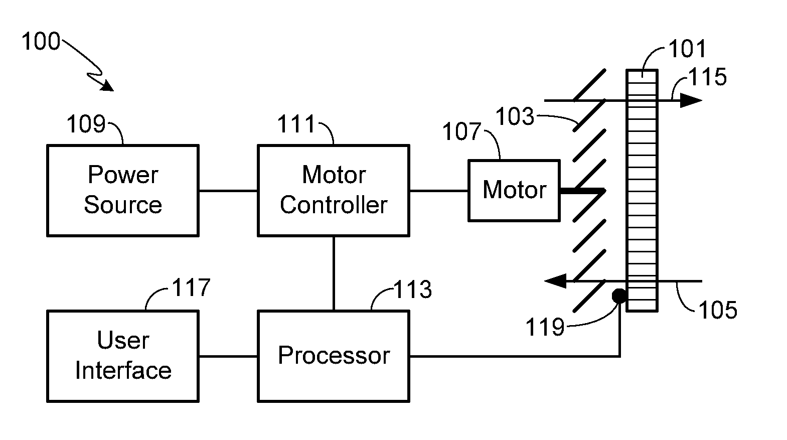
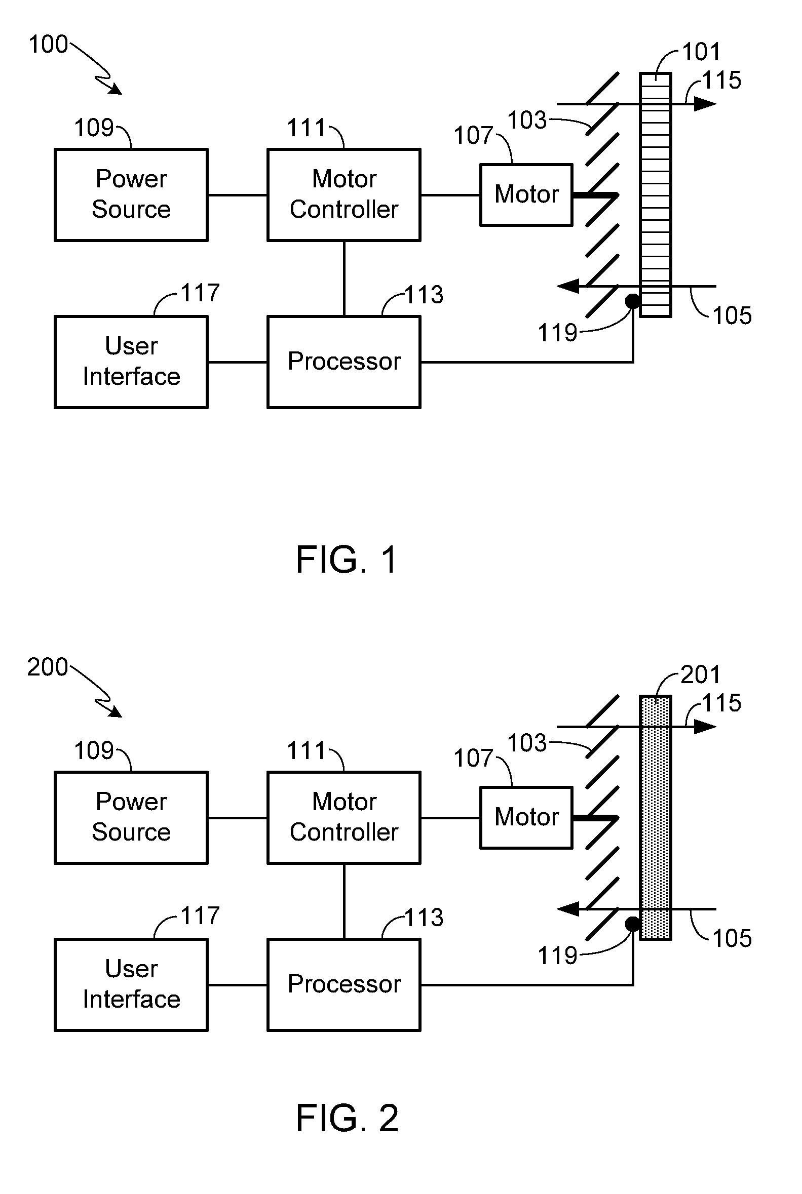
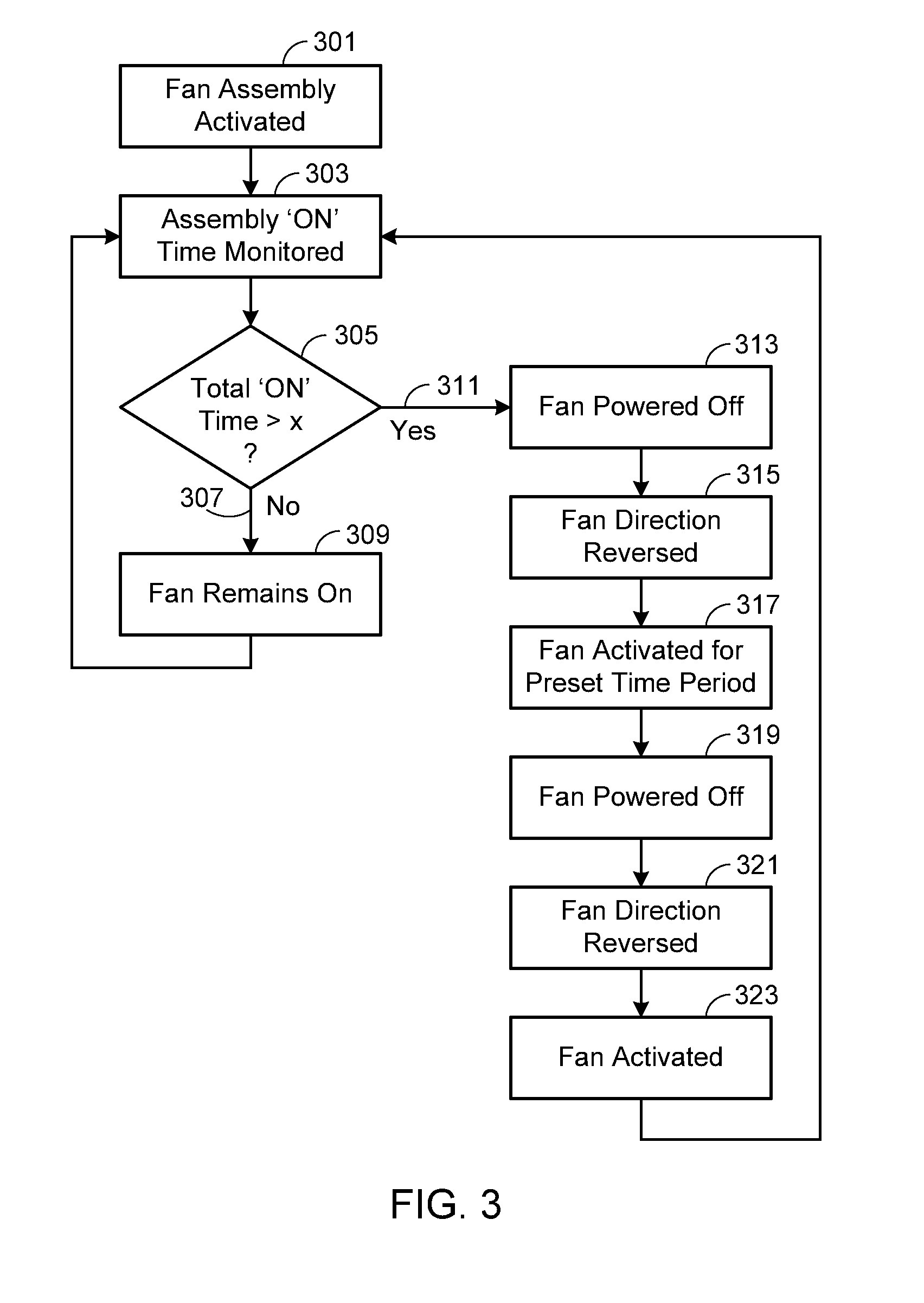
The present invention is a self-cleaning fan assembly that includes a fan, a heat exchanger, and a fan controller. The fan controller controls the direction of rotation of the fan and the processor monitors various factors such as fan usage, total operational time, and current air flow through the heat exchanger. When the fan reaches a predetermined usage value or when the vehicle is not in motion, the processor automatically reverses the fan's direction of rotation for a short period of time to clean the heat exchanger. This helps to maintain the fan's efficiency and ensures optimal performance.

Problems solved by technology

The three most common problems associated with a heat exchanger and blower fan assembly are (i) the failure of the fan motor; (ii) a blockage in the heat exchanger preventing efficient air flow and heat withdrawal; and (iii) a leak in the heat exchanger or coupling conduits.
Although occasionally these problems may be identified by sound, for example if the fan seizes up or the blockage in the heat exchanger impacts fan movement, typically these system malfunctions are only identified when a larger problem occurs, for example when the system that is to be cooled by the heat exchanger overheats.

Method used


Image

  • Self-Cleaning Fan Assembly
  • Self-Cleaning Fan Assembly
  • Self-Cleaning Fan Assembly

Examples


Embodiment Construction

[0022]As used herein, the singular forms “a”, “an” and “the” are intended to include the plural forms as well, unless the context clearly indicates otherwise. The terms “comprises”, “comprising”, “includes”, and / or “including”, as used herein, specify the presence of stated features, integers, steps, operations, elements, and / or components, but do not preclude the presence or addition of one or more other features, integers, steps, operations, elements, components, and / or groups thereof. As used herein, the term “and / or” and the symbol “ / ” are meant to include any and all combinations of one or more of the associated listed items. Additionally, while the terms first, second, etc. may be used herein to describe various steps or calculations, these steps or calculations should not be limited by these terms, rather these terms are only used to distinguish one step or calculation from another. For example, a first calculation could be termed a second calculation, and, similarly, a first...


PUM


Abstract

A self-cleaning fan assembly is provided that can be used to automatically clean the assembly's heat exchanger or air filter. In use, once the system determines that the heat exchanger / air filter should be cleaned, for example based on the total operational time or the number of use cycles for the system, or based on the air flow passing through the heat exchanger / air filter, the controller temporarily reverses the direction of the fan, thereby reversing the flow of air through the heat exchanger / air filter and forcing out dust, dirt and other debris.

Description

FIELD OF THE INVENTION[0001]The present invention relates generally to a fan and, more particularly, to a self-cleaning fan assembly.BACKGROUND OF THE INVENTION[0002]A motor-driven fan is a relatively simple and well-known mechanism used to circulate air. In a common application, the fan blows the air through a heat exchanger, such as a radiator, condenser or evaporator. The air that flows through the heat exchanger may be used as a source of heating or cooling, for example in a car's heating, ventilation and air conditioning (HVAC) system. Alternately, the air flowing through the heat exchanger may be used to alter the temperature of the fluid in the heat exchanger, for example to withdraw the heat generated by another system (e.g., engine, motor, battery pack, cpu, etc.) where the coolant is pumped through the heat exchanger.[0003]The three most common problems associated with a heat exchanger and blower fan assembly are (i) the failure of the fan motor; (ii) a blockage in the hea...

Claims


Application Information

Patent Timeline
IPC IPC(8): F28G13/00
CPCF28G13/00B60H3/0092B60H3/0633F01P7/048F01P11/06F28G15/003
Inventor GAUTHIER, JEAN-PHILIPPE
Owner ATIEVA USA INC
Learn More