
Apparatus and methods for measuring current

a technology of apparatus and current, applied in the field of measuring current, can solve the problems of difficult accurate measurement, inability to make direct current (dc) measurements, and inability to accurately measure,

Active Publication Date: 2016-02-18
ANALOG DEVICES INC
View PDF28 Cites 34 Cited by
  • Summary
  • Abstract
  • Description
  • Claims
  • Application Information

AI Technical Summary

Benefits of technology

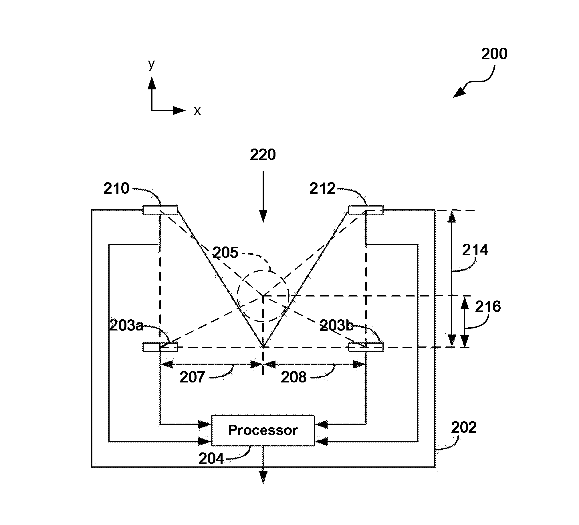
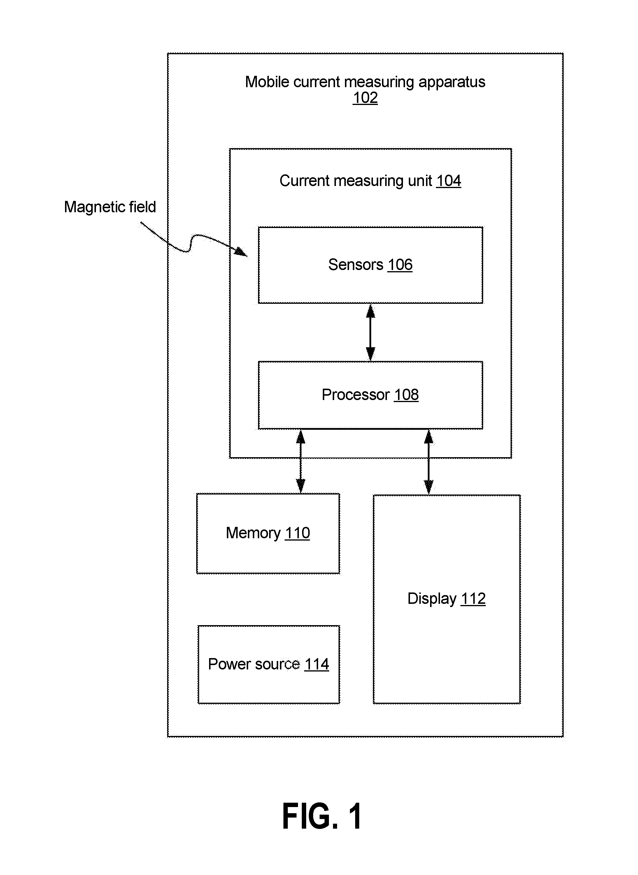
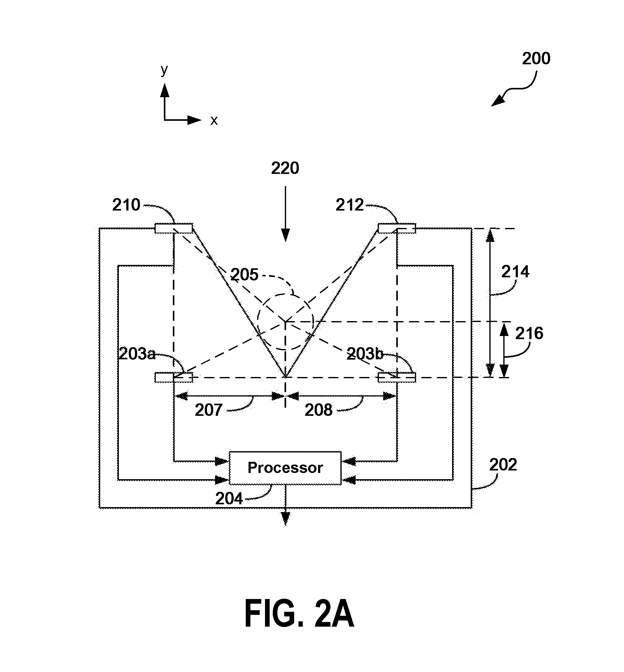
The described technology has several aspects that work together to measure current flowing through a wire. An apparatus is described with magnetic sensors positioned on the sides of an opening into which the wire is placed. Another sensor is used to measure the vertical position of the wire. A processor analyzes the signals from these sensors and generates a measure of the current flowing through the wire based on the difference in signal between the magnetic sensors and the location of the wire in the second dimension. This technology provides a way to accurately measure current flow through wires, which can be useful in various applications.

Problems solved by technology

In particular, accurate current measurement without precise control of the placement of the wire may present various challenges.
It can also be challenging to accurately measure current through the wire remotely when there are other current carrying wires located nearby, as the current flowing though such wires can interfere with the desired current measurement.
However, Rogowski coils cannot make direct current (DC) measurements and can be too bulky for use in tight spaces.

Method used


Image

  • Apparatus and methods for measuring current
  • Apparatus and methods for measuring current
  • Apparatus and methods for measuring current

Examples


Embodiment Construction

[0015]Various aspects of the novel systems, apparatuses, and methods are described more fully hereinafter with reference to the accompanying drawings. Aspects of this disclosure may, however, be embodied in many different forms and should not be construed as limited to any specific structure or function presented throughout this disclosure. Rather, these aspects are provided so that this disclosure will be thorough and complete, and will fully convey the scope of the disclosure to those skilled in the art. Based on the teachings herein, one skilled in the art should appreciate that the scope of the disclosure is intended to cover any aspect of the novel systems, apparatuses, and methods disclosed herein, whether implemented independently of or combined with any other aspect. For example, an apparatus may be implemented or a method may be practiced using any number of the aspects set forth herein. In addition, the scope is intended to encompass such an apparatus or method which is pr...


PUM


Abstract

In an embodiment, a body of apparatus includes an opening, such as a V-shaped jaw, that deterministically locates a position of a wire in at least one dimension when the wire is placed in the opening. The apparatus also includes a plurality of sensors. At least one differential signal can be generated from signals from magnetic sensors, such as anisotropic magnetoresistance (AMR) sensors, of the plurality of sensors to cancel out common mode interference. An additional sensor of the plurality of sensors provides an output from which the location of the wire in another dimension is determined. The current flowing through the wire can be derived from at least the at least one differential signal and the location of the wire the other dimension.

Description

BACKGROUND[0001]1. Field[0002]The described technology generally relates to measuring current and, more specifically, to apparatus and methods for sensing and / or measuring current flowing through a wire.[0003]2. Description of the Related Art[0004]Accurate measurement of current through a wire remotely (e.g., without breaking the wire or coming into contact with it) is useful for diagnostic, operational, and protection purposes in many applications, such as industrial and automotive applications. In particular, accurate current measurement without precise control of the placement of the wire may present various challenges. It can also be challenging to accurately measure current through the wire remotely when there are other current carrying wires located nearby, as the current flowing though such wires can interfere with the desired current measurement. One commonly used technique for alternating current (AC) measurements is using a Rogowski coil, which does not depend on the preci...

Claims


Application Information

Patent Timeline
Patent Type & Authority Applications(United States)
IPC IPC(8): G01R15/20G01R33/09
CPCG01R15/207G01R33/096G01R15/205G01R15/202
Inventor SHARMA, YOGESH JAYARAMANCARTER, NATHAN R.SONGATIKAMAS, TEERACRONIN, BRENDAN
Owner ANALOG DEVICES INC
Learn More