Registration calculation of three-dimensional scanner data performed between scans based on measurements by two-dimensional scanner

a two-dimensional scanner and scanner data technology, applied in the direction of distance measurement, instruments, using reradiation, etc., can solve the problems of increasing the cost of the scanning project, difficult to remove the need for a user to carry out manual registration steps, and relatively time-consuming manual registration procedures

Active Publication Date: 2016-02-18
FARO TECH INC
View PDF0 Cites 51 Cited by
  • Summary
  • Abstract
  • Description
  • Claims
  • Application Information

AI Technical Summary

Problems solved by technology

Some registration procedures involve relatively time-consuming manual procedures such as identifying by a user each target and matching the targets obtained by the scanner in each of the different registration positions.
However, even with the simplifications provided by the methods of '352, it is today still difficult to remove the need for a user to carry out the manual registration steps as described above.
This adds to the cost of the scanning project.
Furthermore, the manual registration process sometimes reveals that the overlap between adjacent scans was insufficient to provide proper registration.
When such problems occur, the operator must return to the site to obtain additional scans.
In some cases, it is not possible to return to a site.
A building that was available for scanning at one time may be impossible to access at a later time.
A forensics scene of an automobile accident or a homicide is often not available for taking of scans for more than a short time after the incident.

Method used


Image

  • Registration calculation of three-dimensional scanner data performed between scans based on measurements by two-dimensional scanner
  • Registration calculation of three-dimensional scanner data performed between scans based on measurements by two-dimensional scanner
  • Registration calculation of three-dimensional scanner data performed between scans based on measurements by two-dimensional scanner

Examples


Embodiment Construction

[0032]The present invention relates to a device that includes a 3D scanner and a 2D scanner working cooperatively to provide automatic registration of 3D scans.

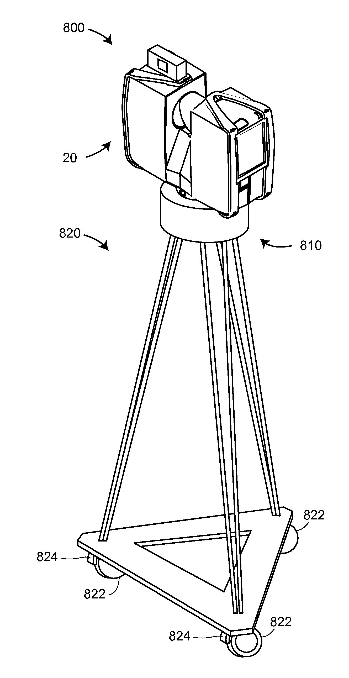
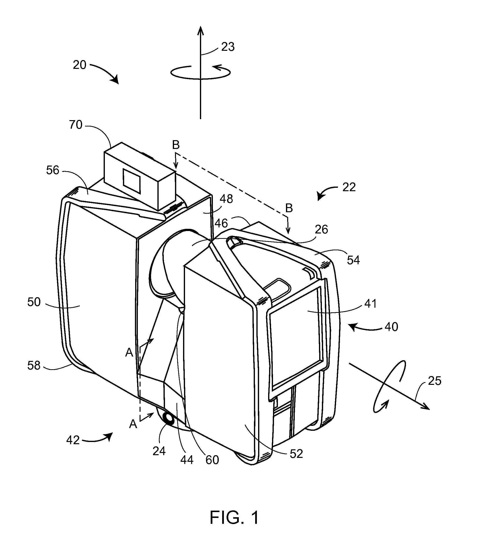
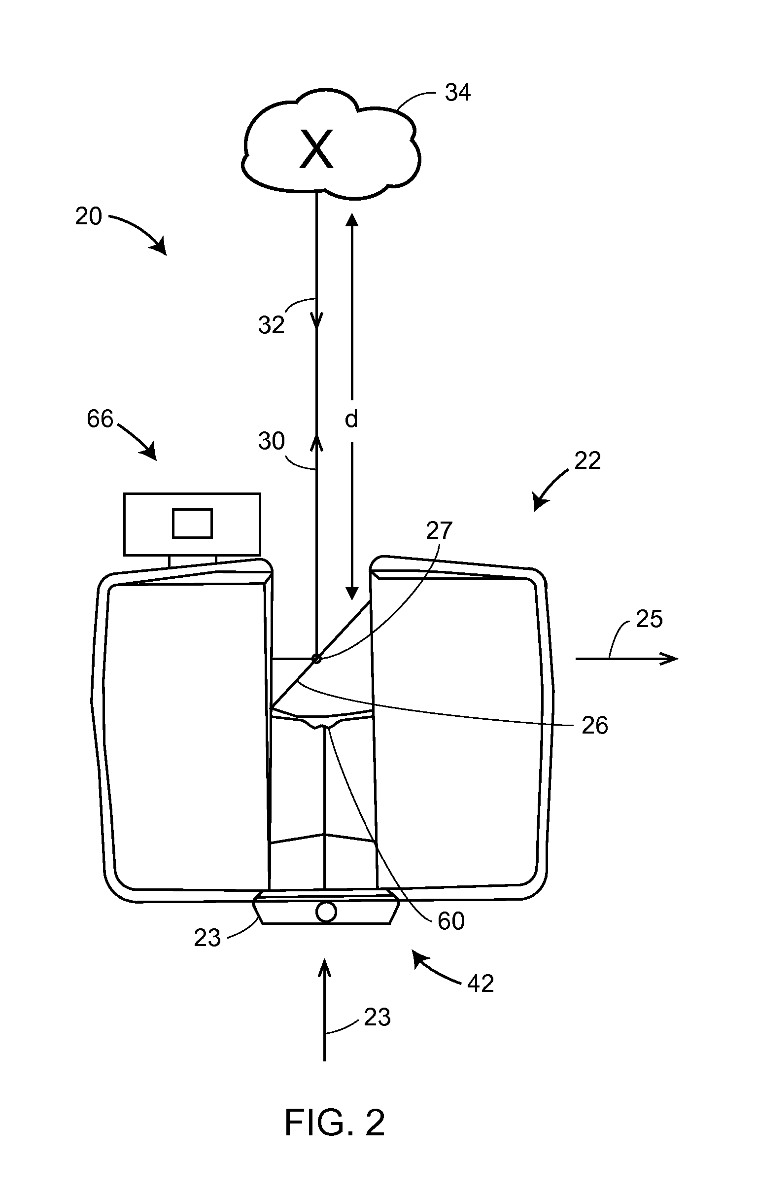
[0033]Referring now to FIGS. 1-3, a laser scanner 20 is shown for optically scanning and measuring the environment surrounding the laser scanner 20. The laser scanner 20 has a measuring head 22 and a base 24. The measuring head 22 is mounted on the base 24 such that the laser scanner 20 may be rotated about a vertical axis 23. In one embodiment, the measuring head 22 includes a gimbal point 27 that is a center of rotation about the vertical axis 23 and a horizontal axis 25. The measuring head 22 has a rotary mirror 26, which may be rotated about the horizontal axis 25. The rotation about the vertical axis may be about the center of the base 24. The terms vertical axis and horizontal axis refer to the scanner in its normal upright position. It is possible to operate a 3D coordinate measurement device on its side or upside down...


PUM


Abstract

A method for measuring and registering three-dimensional (3D) coordinates by measuring 3D coordinates with a 3D scanner in a first registration position, measuring two-dimensional (2D) coordinates with a 2D scanner while moving from the first registration position to a second registration position, measuring 3D coordinates with the 3D scanner at the second registration position, and determining a correspondence among targets in the first and second registration positions while moving between the second registration position and a third registration position.

Description

CROSS-REFERENCE TO RELATED APPLICATIONS[0001]The present application is a continuation-in-part of U.S. patent application Ser. No. 14 / 559,290, filed Dec. 3, 2014, which claims the benefit of International Patent Application No. PCT / IB2013 / 003082, filed Sep. 27, 2013, which claims the benefit of German Patent Application No. 10 2012 109 481.0, filed Oct. 5, 2012 and of U.S. Provisional Patent Application No. 61 / 716,845, filed Oct. 22, 2012, the contents of all of which are incorporated by reference herein.BACKGROUND OF THE INVENTION[0002]U.S. Pat. No. 8,705,016 ('016) describes a laser scanner which, through use of a rotatable mirror, emits a light beam into its environment to generate a three-dimensional (3D) scan. The contents of this patent are incorporated herein by reference.[0003]The subject matter disclosed herein relates to use of a 3D laser scanner time-of-flight (TOF) coordinate measurement device. A 3D laser scanner of this type steers a beam of light to a non-cooperative ...

Claims


Application Information

Patent Timeline
Patent Type & Authority Applications(United States)
IPC IPC(8): G01S17/42G01S7/48G01S7/481G01S17/10G01S17/86G01S17/87G01S17/89
CPCG01S17/42G01S7/4817G01S7/4808G01S17/89G01C7/04G01C15/002G01S17/36G01S17/87G01S7/003G01S7/4813G05D1/024G05D1/0274G09B29/004G05D2201/0207G01S17/10G01S17/86
Inventor ZWEIGLE, OLIVERBECKER, BERND-DIETMARBECKER, REINHARD
Owner FARO TECH INC
Why Eureka
Try Eureka