Laser radar for three-dimensional scanning

a laser radar and three-dimensional scanning technology, applied in the direction of distance measurement, height/levelling measurement, instruments, etc., can solve the problems of difficult three-dimensional detection of targets, limited detection range, and inability to detect laser beams reflected externally from concave mirrors out of scan planes. to achieve the effect of reducing the load imposed in changing the orientation

Inactive Publication Date: 2014-03-25
DENSO WAVE INC
View PDF10 Cites 74 Cited by
  • Summary
  • Abstract
  • Description
  • Claims
  • Application Information

AI Technical Summary

Benefits of technology

[0013]Hence, it is desired to realize, in a laser radar enabling three-dimensional recognition of targets around the laser radar, a configuration that enables high-speed laser beam scanning, while reducing size and weight of the laser radar.
[0016]In the process of the relative movement of the line scan position on the deflecting surface, the laser beam to be moved in the virtual plane is ensured to be incident on the individual plurality of reflecting surfaces. Thus, the laser beam is reflected by the individual reflecting surfaces in spite of the change of orientation of the deflecting surface due to the rotation of the deflector. In this way, the laser beam is three-dimensionally scanned around the laser radar, changing its inclination angle (angle with respect to the horizontal plane). In particular, since the laser beam can be radiated to the deflecting surface based on line scanning (one-dimensional scan), laser scanning is conducted for the deflecting surface at high speed, without increasing the size of the driving mechanism or complicating the driving mechanism. Further, the laser radar is able to three-dimensionally recognize the presence of a target around the laser radar at higher speed.
[0020]With this configuration, the orientation of the first scanning member only has to be changed every N-time rotation of the deflector. Thus, the load imposed in changing the orientation is reduced, compared to the configuration in which the orientation is changed several times during one rotation of the deflector. In particular, in the configuration of changing the orientation several times in one rotation, it is difficult to rotate the deflector at high speed because the time taken for changing the orientation several times has to be taken into account. In this regard, the change of orientation on an N-time rotation basis as described above enables high-speed rotation of the deflector, while facilitating the change at appropriate timing without delay. Thus, the laser radar is more advantageously used in conducting high-speed three-dimensional recognition of targets.

Problems solved by technology

However, this raises a problem that the detection range is limited to a plane.
Specifically, since scanning is limited to a predetermined plane (scan plane), a laser beam reflected externally from the concave mirror which goes out of the scan plane is not able to conduct detection.
Even when a target is present in the scan plane, it is difficult to three-dimensionally detect the target.
However, the method of pivotally moving the two-dimensional distance-measuring unit as a whole together with its casing, as disclosed in JP-2008-134163-A, unavoidably increases the size of the operating mechanism (second rotating mechanism and the driving source (second motor)).
This is quite disadvantageous from the aspect of reducing weight and size of the apparatus.
Further, from the structural viewpoint of driving the two-dimensional distance-measuring unit in its entirety, mechanical or electrical load caused in the operating mechanism or the driving source is unavoidably large.
Thus, considerably large torque, electrical power and the like are required in driving the unit, making it problematically difficult to perform scanning at high speed.
As a result, high-speed scan is encumbered.
However, in order to well perform three-dimensional recognition in a large rotation range using the configuration shown by JP-2009-098111-A, the pivoted mirror is required to be moved in a complicated manner.
However, it is difficult to increase speed in such a complicated pivotal movement, and the complicated pivotal movement necessarily involves a complicated configuration and control method.
In particular, in the configuration of changing the orientation several times in one rotation, it is difficult to rotate the deflector at high speed because the time taken for changing the orientation several times has to be taken into account.

Method used


Image

  • Laser radar for three-dimensional scanning
  • Laser radar for three-dimensional scanning
  • Laser radar for three-dimensional scanning

Examples


first embodiment

[0059](First Embodiment)

[0060]Referring to FIGS. 1 to 14 and FIG. 29, a first embodiment to which the present invention is applied is described.

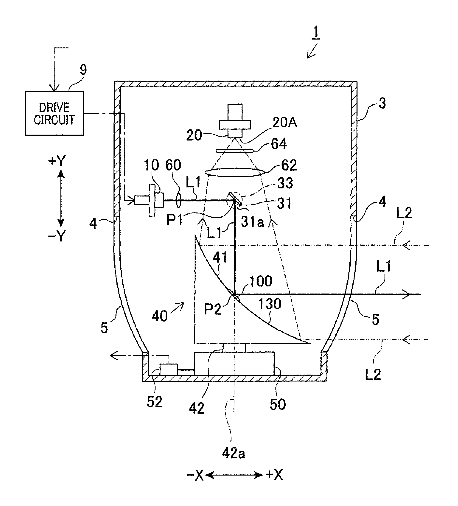
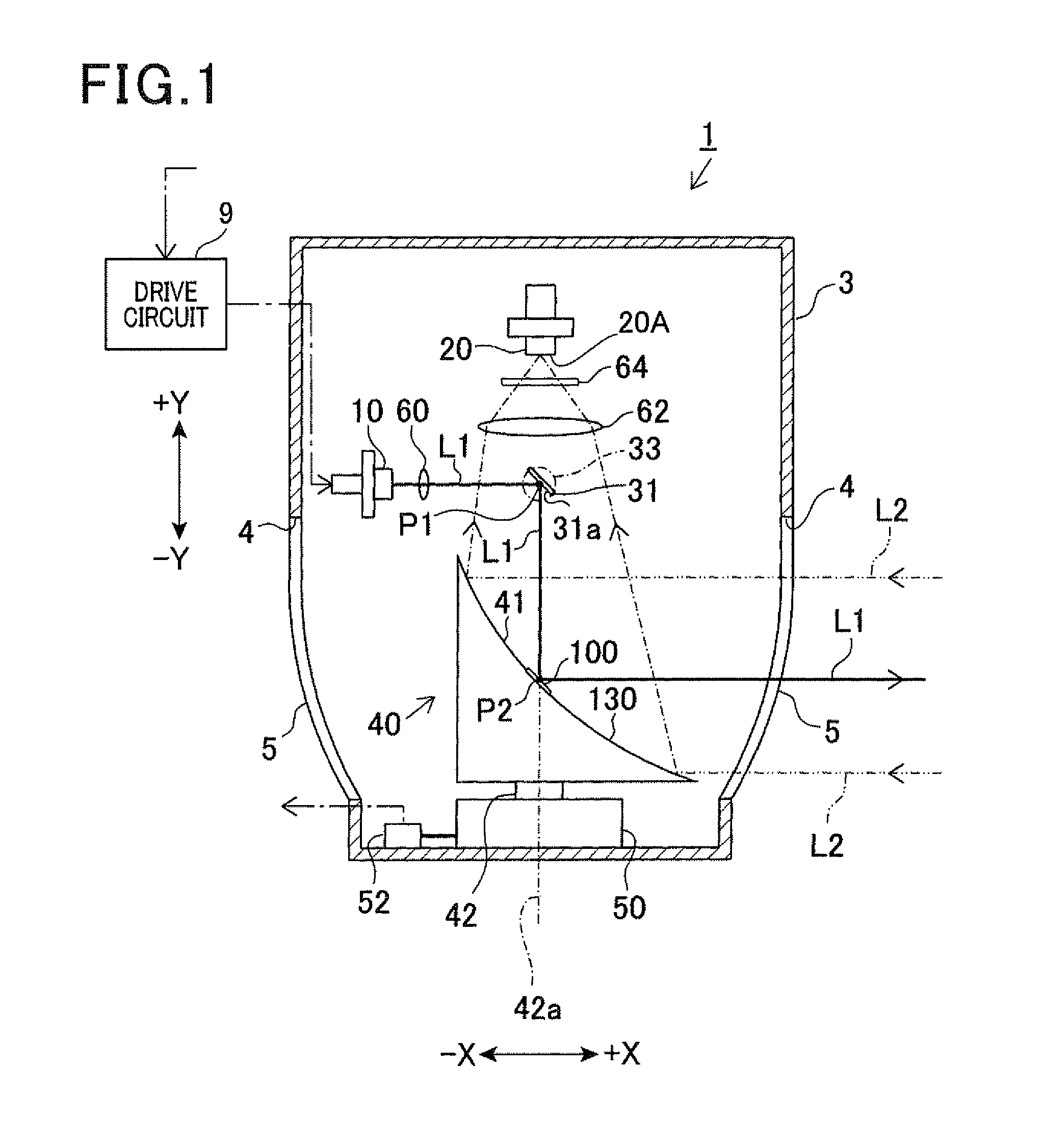
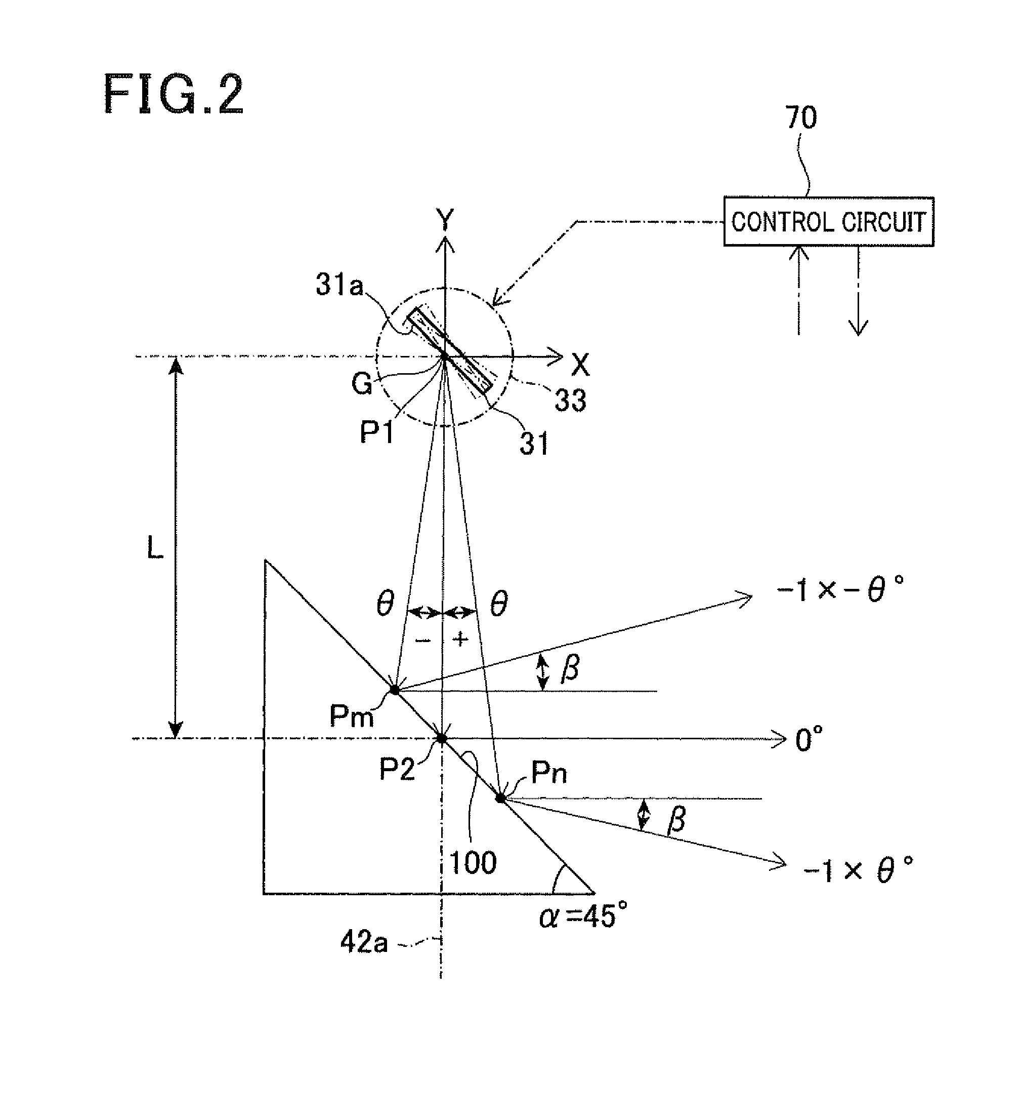
[0061]First, general configuration of a laser radar 1 according to the first embodiment is described. FIG. 1 is a schematic cross-sectional view illustrating the laser radar 1. FIG. 2 is a diagram illustrating a correlation between angle of laser beam radiated to a deflector and a radiation angle from the deflector.

[0062]As shown in FIG. 1, the laser radar 1 includes a laser diode 10 and a photodiode 20. The laser radar 1 is configured to detect a distance to and a direction of a target of detection.

[0063]The laser diode 10 corresponds to the laser beam generating means and is made up of a known laser diode. The laser diode 10 is supplied with pulsed current from a drive circuit 9 to intermittently emit a pulsed laser beam (laser beam L1) at a predetermined interval according to the pulsed current.

[0064]The photodiode 20 is made up of a know...

second embodiment

[0141](Second Embodiment)

[0142]Referring now to FIGS. 15 to 28 and FIG. 30, hereinafter is described a second embodiment of the present invention.

[0143]FIG. 15 is a schematic perspective view illustrating the vicinity of a concave mirror of a laser radar according to the second embodiment. FIG. 16 is a diagram illustrating a correlation between angle of laser beam radiated to a deflector and radiation angle from the deflector, according to the second embodiment. FIG. 17 is a perspective view illustrating a configuration in the vicinity of a scan beam reflector of the laser radar illustrated in FIG. 15. FIG. 18 is a plan view illustrating a configuration in the vicinity of the scan beam reflector of the laser radar illustrated in FIG. 15. FIG. 19A is a schematic cross-sectional view taken along an azimuth direction of 0° to 180° of FIG. 18. FIG. 19B is a schematic cross-sectional view taken along an azimuth direction of 45° to −135° of FIG. 5.

[0144]In the present embodiment as well, ...


PUM


Abstract

In a laser radar, a first scanning member scans a laser beam in a virtual plane passing through an axis. A control means controls displacements of the first scanning member to change a scan beam angle in the plane. A second scanning member deflects the scanned laser beam and again scans the deflected laser beam toward an external space. A light collecting means collects reflected light. A driving means rotates both the second scanning member and the light collecting means about the axis. The second scanning member has a deflecting surface to deflect the laser beam. The deflecting surface is formed around the axis and has a plurality of reflecting surfaces coaxially arranged centering on the axis. The reflecting surfaces have different inclinations with respect to a horizontal plane perpendicular to the axis.

Description

CROSS-REFERENCE TO RELATED APPLICATION[0001]This application is based on and claims the benefit of priority from earlier Japanese Patent Application No. 2011-077731 filed Mar. 31, 2011, the description of which is incorporated herein by reference.BACKGROUND OF THE INVENTION[0002]1. Technical Field of the Invention[0003]The present invention relates to a laser radar for three dimensional scanning, and in particular to a laser radar that three-dimensionally scan the space outside the laser radar using a laser beam.[0004]2. Related Art[0005]It is well known to use a laser beam to detect a distance to a target or direction of the target. A patent document JP-2789741-B, for example, discloses a device relating to such a technique. The device disclosed in this patent document includes a light isolator on the axis of a laser beam emitted from a laser beam generating means to transmit the laser beam and to reflect the light reflected from a target to a detecting means. Further, the device i...

Claims


Application Information

Patent Timeline
Patent Type & Authority Patents(United States)
IPC IPC(8): G01C3/08
CPCG01S7/4817G01S17/42
Inventor TANAKA, HIDEYUKIMITSUNO, YOSHIKI
Owner DENSO WAVE INC
Why Eureka
Try Eureka