Eureka AIR delivers breakthrough ideas for toughest innovation challenges, trusted by R&D personnel around the world.

Soft start circuit

Active Publication Date: 2016-02-18
ROHM CO LTD
View PDF39 Cites 2 Cited by
  • Summary
  • Abstract
  • Description
  • Claims
  • Application Information

AI Technical Summary

Benefits of technology

The patent text describes a soft start circuit that can keep a soft start time constant even as the circuit scale increases. The circuit generates a soft start voltage that slowly rises from a minimum to a maximum that is higher than a reference voltage and changes based on the reference voltage. This allows for a smooth and reliable start-up of electronic equipment. The technical effect of this invention is to provide a flexible and efficient solution for controlling the soft start time of electronic equipment without increasing circuit size.

Problems solved by technology

However, in the conventional soft start circuit, there is a problem that if it is attempted to keep the soft start time constant irrespective of a set target value of the output voltage, a circuit scale becomes large unnecessarily.

Method used


Image

  • Soft start circuit
  • Soft start circuit
  • Soft start circuit

Examples


first embodiment

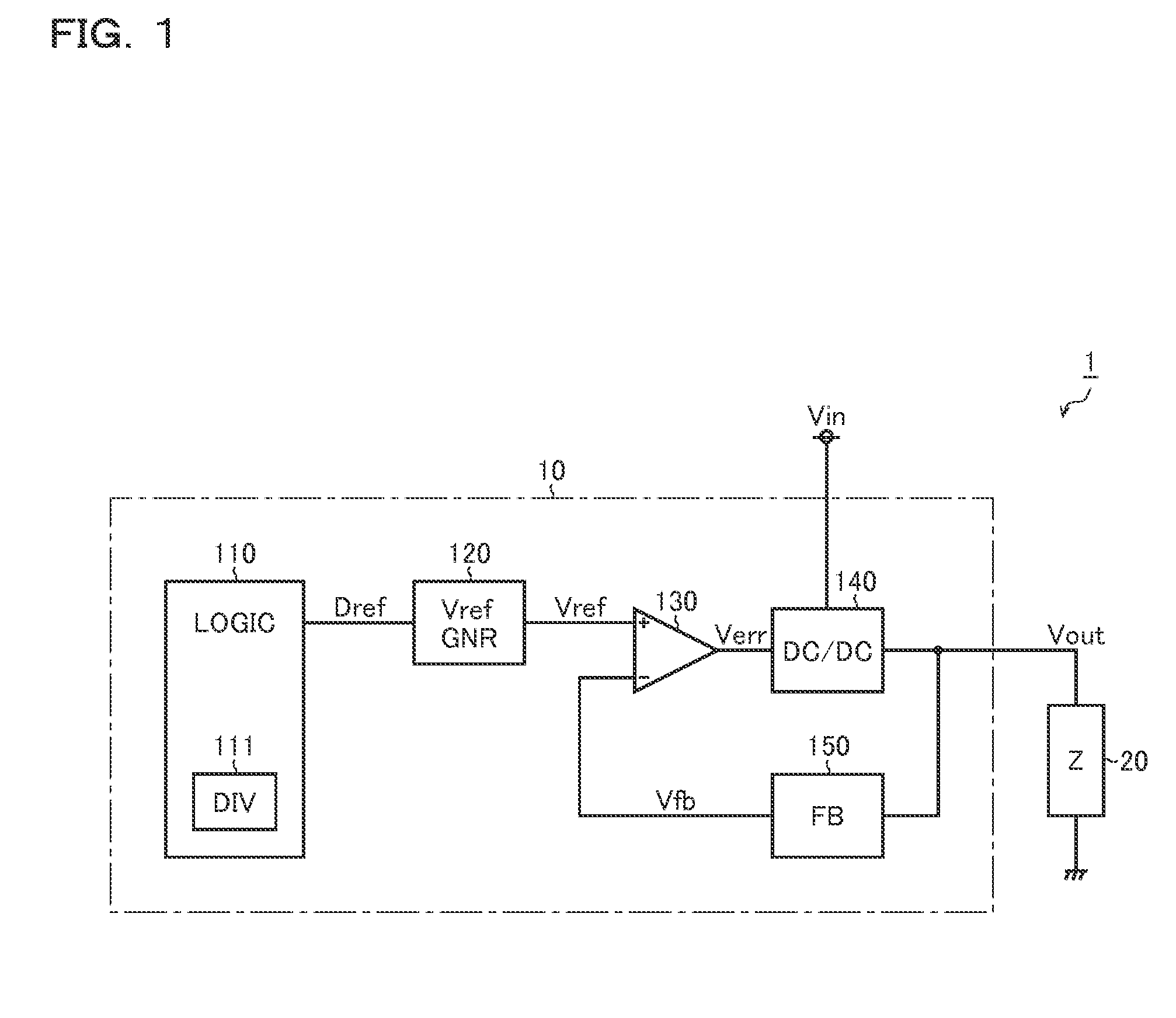
[0021]FIG. 1 is a view showing a whole structure (first embodiment of the power source apparatus 10) of the electronic apparatus 1. The electronic apparatus 1 according to the present structural example has the power source apparatus 10 that generates an output voltage Vout from an input voltage Vin, and a load 20 that is supplied with the output voltage Vout from the power source apparatus 10 to operate.

[0022]The power source apparatus 10 includes a logic circuit 110, a reference voltage generation circuit 120, an error amplifier 130, a DC / DC converter 140, and a feedback voltage generation circuit 150.

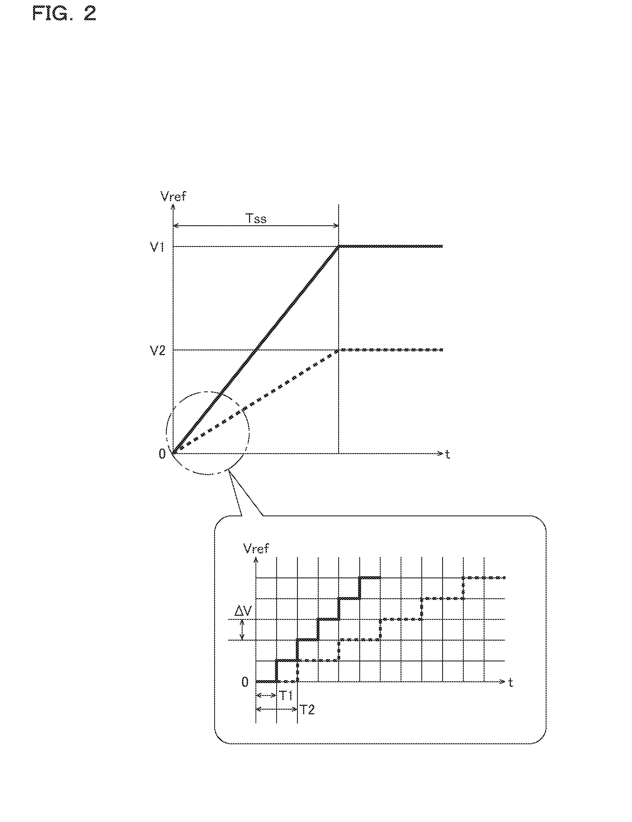
[0023]The logic circuit 110 increases an m-bit digital reference signal Dref from the minimum value (=00h (0d)) to the last value in increments of one in such a manner that the output voltage Vout rises slowly when the power source apparatus 10 is started up.

[0024]In the meantime, the logic circuit 110 sets the last value of the digital reference signal Dref in accordance with a targ...

second embodiment

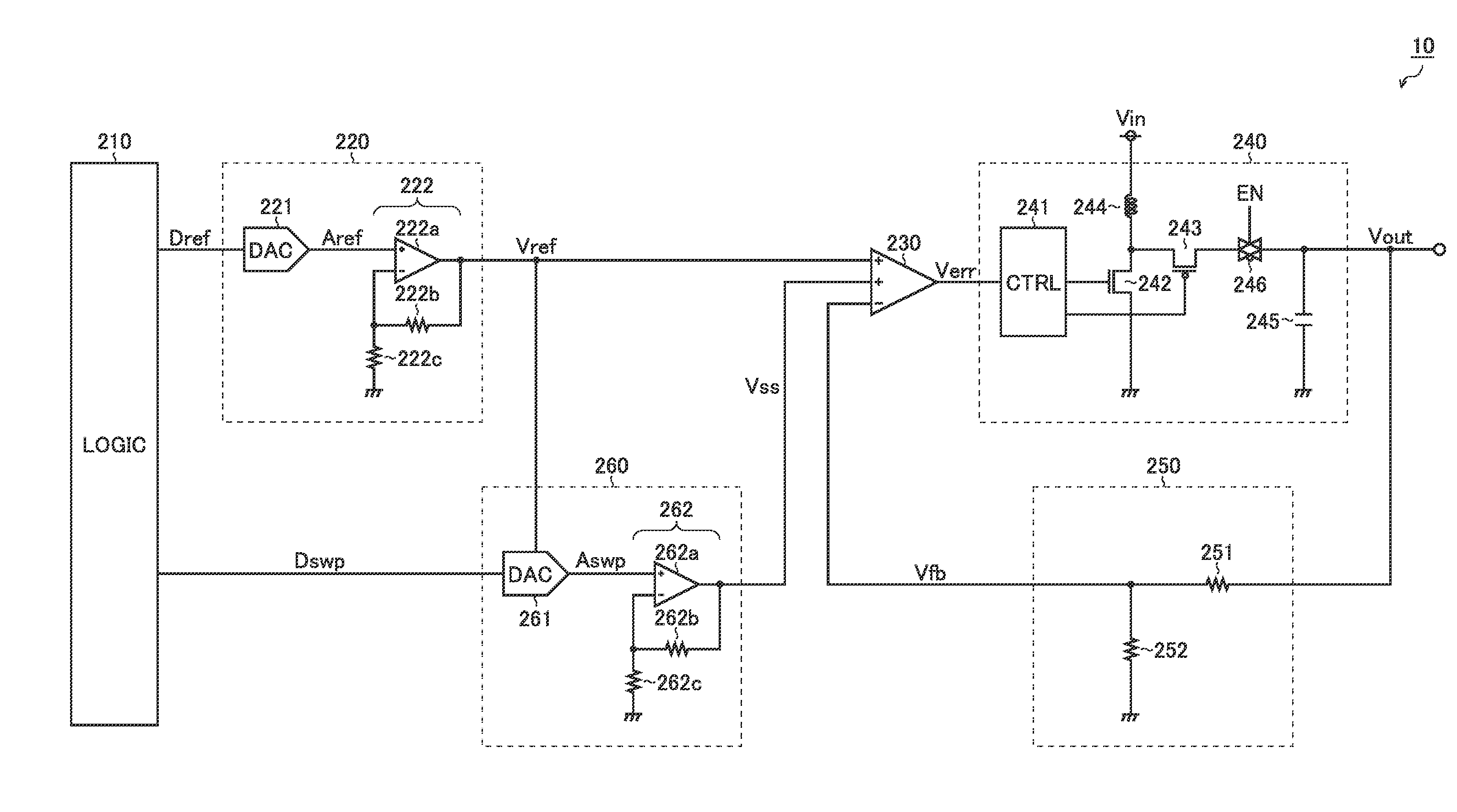
[0036]FIG. 3 is a view showing a second embodiment of the power source apparatus 10. The power source apparatus 10 according to the present embodiment is a step-up type switching power source apparatus that generates the desired output voltage Vout by stepping up the input voltage Vin, and includes a logic circuit 210, a reference voltage generation circuit 220, an error amplifier 230, a DC / DC converter 240, a feedback voltage generation circuit 250, and a soft start circuit 260.

[0037]The logic circuit 210 generates the m-bit digital reference signal Dref in accordance with the target value of the output voltage Vout. Describing more specifically, the logic circuit 210 sets the digital reference signal Dref at a larger value as the target value of the output voltage Vout becomes higher; in contrast, the logic circuit 210 sets the digital reference signal Dref at a smaller value as the target value of the output voltage Vout becomes lower. In the meantime, the target value of the out...


PUM


Abstract

A soft start circuit accepts an input of a reference voltage set arbitrarily, and generates a soft start voltage that takes a predetermined sweep time to slowly rise from a predetermined lowest value to a highest value that is higher than the reference voltage and changes in accordance with the reference voltage.

Description

CROSS-REFERENCE TO RELATED APPLICATIONS[0001]This application is based on the following Japanese Patent Application, the contents of which are hereby incorporated by reference:[0002](1) Patent Application No.: 2014-165855 (the filing date: Aug. 18, 2014)BACKGROUND OF THE INVENTION[0003]1. Field of the Invention[0004]The present invention relates to a soft start circuit.[0005]2. Description of Related Art[0006]Conventionally, many of power source apparatuses that generate an output voltage from an input voltage have a soft start circuit, as a device for curbing a rush current at a startup time, which takes a predetermined soft start time to raise slowly the output voltage.[0007]In the meantime, as an example of the prior art relevant to the above description, there is JP-A-2005-51956.[0008]However, in the conventional soft start circuit, there is a problem that if it is attempted to keep the soft start time constant irrespective of a set target value of the output voltage, a circuit ...

Claims


Application Information

Patent Timeline
IPC IPC(8): H02M1/36H02M3/156
CPCH02M3/156H02M1/36
Inventor SUMII, RYOSUKESATO, KIMINOBU
Owner ROHM CO LTD
Why Eureka
Eureka Blog
Learn More