Laminated bottle

a technology of laminated bottles and cylinders, applied in the field of laminated bottles, can solve the problems of unstable discharge of contents, increased contents remaining, and so as to prevent a failure to discharge or increase the amount of contents remaining, reduce the lifting effect of inner layers, and facilitate the effect of impor

Active Publication Date: 2016-02-25
YOSHINO KOGYOSHO CO LTD
View PDF2 Cites 12 Cited by
  • Summary
  • Abstract
  • Description
  • Claims
  • Application Information

AI Technical Summary

Benefits of technology

[0071]According to the laminated bottle of the present invention, it is possible to efficiently limit lift of an inner layer, and to prevent a discharge failure or an increase in the amount of contents remaining.
[0072]In addition, according to the laminated bottle of the present invention, outside air can be smoothly imported into a space between an inner layer and an outer layer.

Problems solved by technology

Additionally, in a laminated bottle combined with no dispenser, the inner layers of laminated bottles after the volume-reduction deformation thereof may easily vary in shape, and the discharge of the contents may become unstable.
In the laminated bottle in which the inner layer has lifted up in this way, a discharge failure or an increase in the amount of contents remaining (increase in the amount of contents remaining in the bottle at the time a discharge-disabled state is reached) may be caused.

Method used


Image

  • Laminated bottle
  • Laminated bottle
  • Laminated bottle

Examples


first embodiment

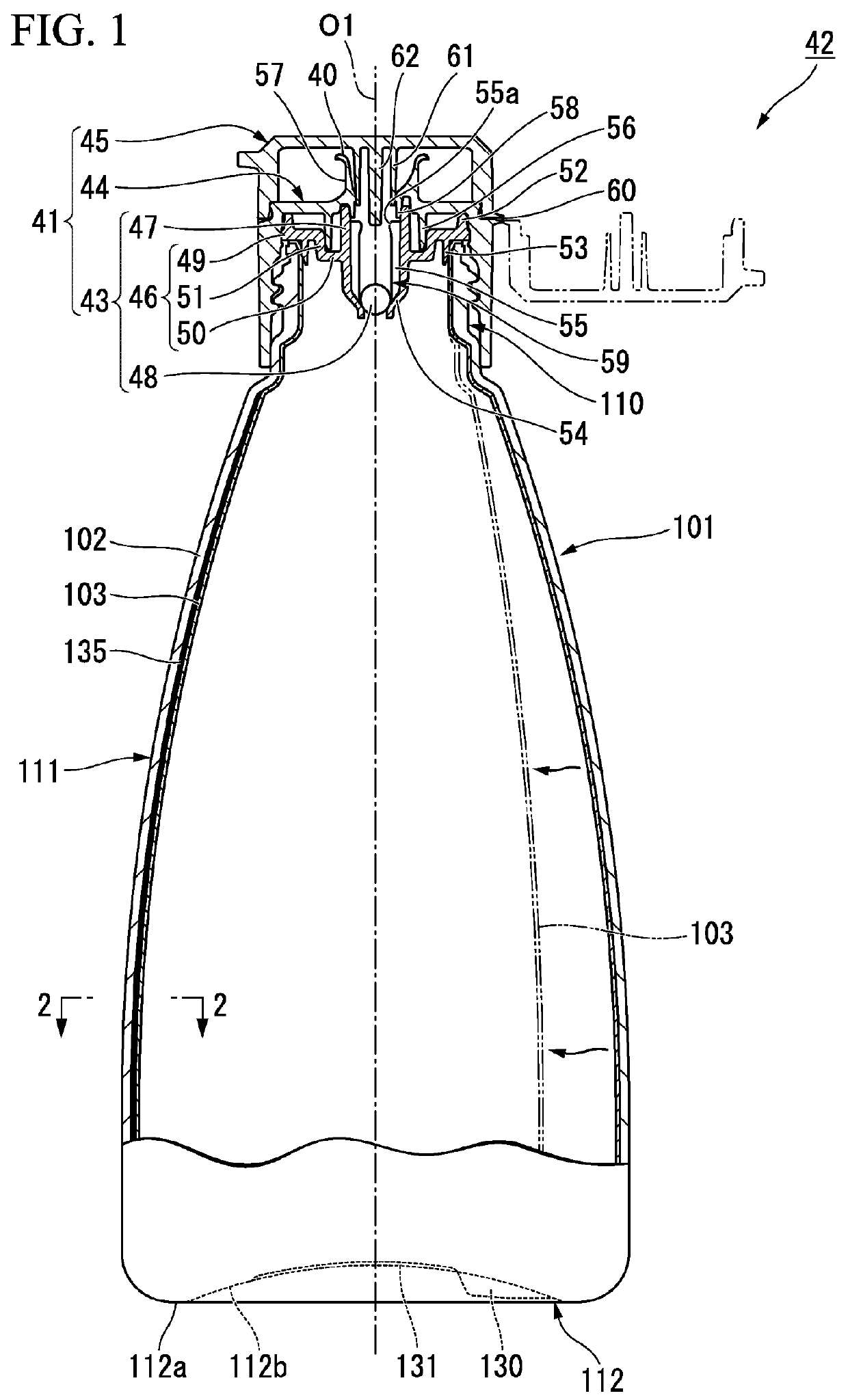
[0112]Hereinafter, a first embodiment of a laminated bottle of the present invention is described with reference to the drawings.

(Structure of Laminated Bottle)

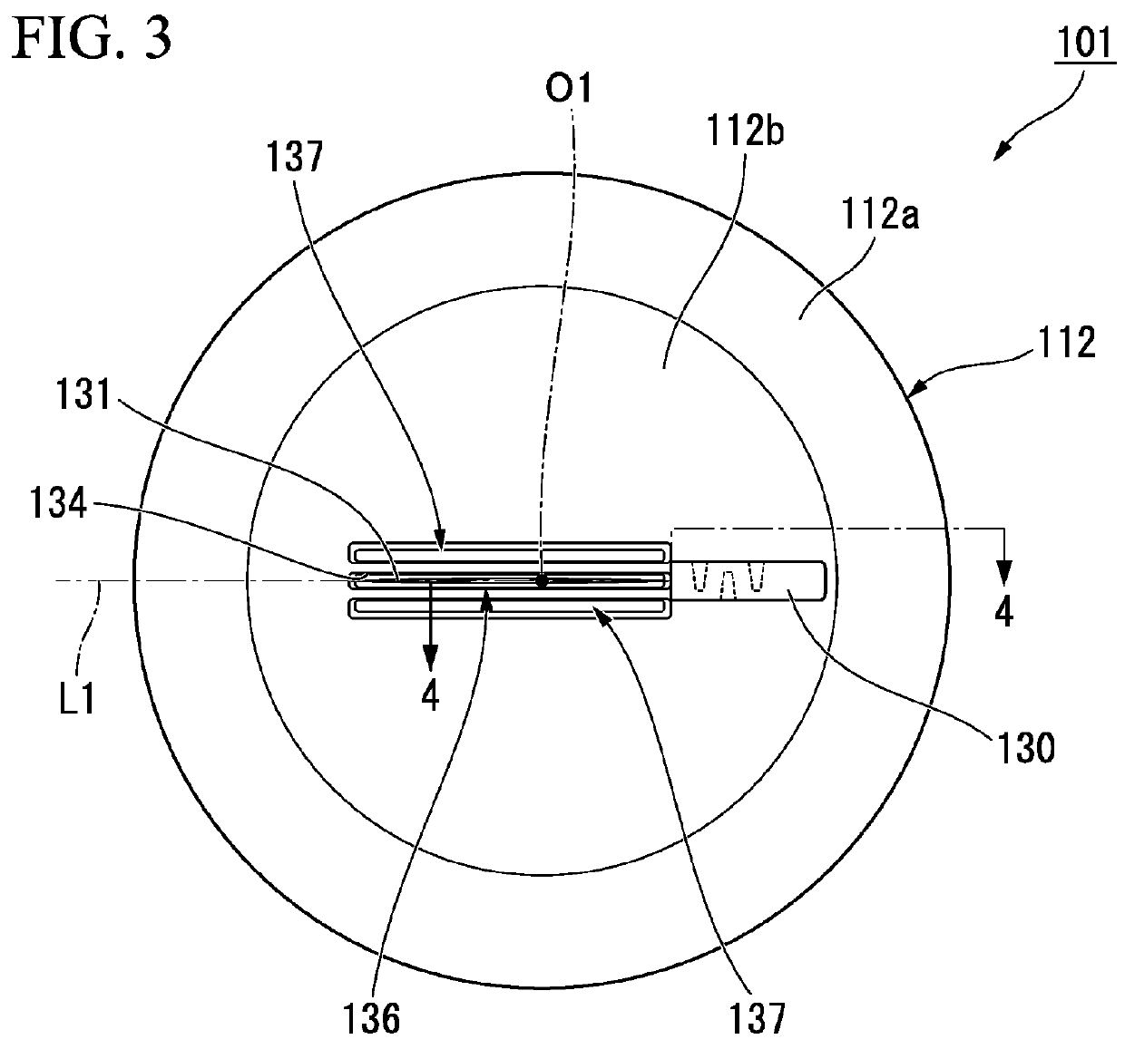
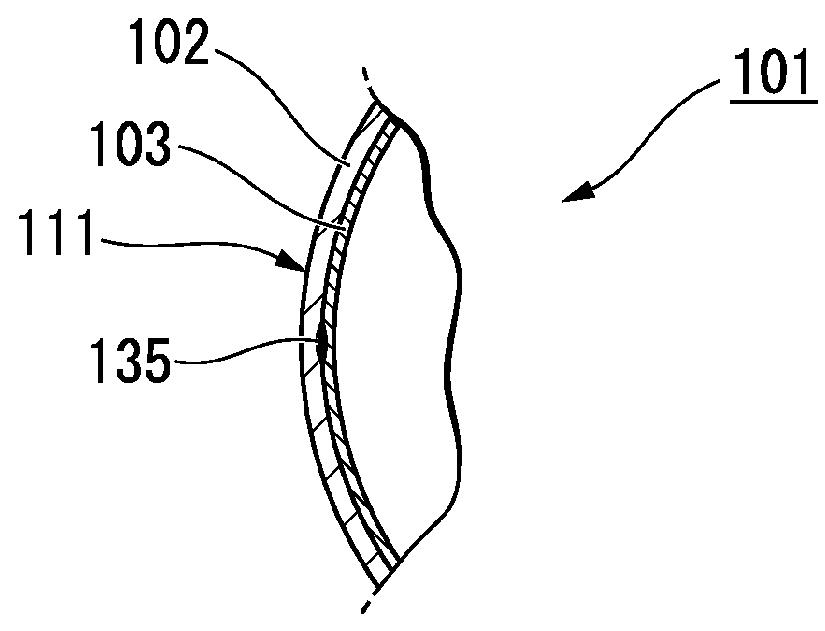
[0113]As shown in FIGS. 1 and 2, a laminated bottle 101 of this embodiment includes an outer layer 102 configured to accept squeeze deformation, and a flexible inner layer 103 in which contents (not shown) are contained and which is configured to perform volume-reduction deformation (shrinkage deformation) in accordance with a decrease in the amount of contents. The laminated bottle 101 is a delamination bottle (a lamination-separable container) formed in a cylindrical shape with a bottom, in which the inner layer 103 is laminated onto an inner surface of the outer layer 102 and is separable from the inner surface.

[0114]In this embodiment, the “outer layer” denotes an outer container forming an outer portion of the laminated bottle 101, and the “inner layer” denotes an inner container (inner bag) forming an inner portion of t...

second embodiment

[0170]Hereinafter, a second embodiment of the laminated bottle of the present invention is described with reference to the drawings.

(Structure of Laminated Bottle)

[0171]As shown in FIGS. 8 to 10, a laminated bottle 1 of this embodiment includes an outer layer 2, and a flexible inner layer 3 in which contents (not shown) are contained and which is configured to perform volume-reduction deformation (shrinkage deformation) in accordance with a decrease in the amount of contents. The laminated bottle 1 is a delamination bottle (a lamination-separable container) formed in a cylindrical shape with a bottom, in which the inner layer 3 is separably laminated onto an inner surface of the outer layer 2.

[0172]In this embodiment, the “outer layer” denotes an outer container forming an outer portion of the laminated bottle 1, and the “inner layer” denotes an inner container (inner bag) forming an inner portion of the laminated bottle 1.

[0173]The outer layer 2 and the inner layer 3 are formed of,...

third embodiment

[0219]Hereinafter, a third embodiment of the laminated bottle of the present invention is described with reference to the drawings.

(Structure of Laminated Bottle)

[0220]As shown in FIGS. 16 and 17, a laminated bottle 201 of this embodiment includes an outer layer 202 configured to accept squeeze deformation, and a flexible inner layer 203 in which contents (not shown) are contained and which is configured to perform volume-reduction deformation (shrinkage deformation) in accordance with a decrease in the amount of contents. The laminated bottle 201 is a delamination bottle (a lamination-separable container) formed in a cylindrical shape with a bottom, in which the inner layer 203 is separably laminated onto an inner surface of the outer layer 202.

[0221]In this embodiment, the “outer layer” denotes an outer container which forms an outer portion of the laminated bottle 201, and the “inner layer” denotes an inner container (inner bag) which forms an inner portion of the laminated bottl...


PUM


Abstract

The laminated bottle formed in a cylindrical shape with a bottom includes: an outer layer; and a flexible inner layer laminated onto an inner surface of the outer layer and being separable from the inner surface. A bottom section of the outer layer positioned at a bottle bottom portion is provided with: a holding rib pinching and holding the inner layer; an intake hole disposed at a position different from the holding rib and allowing outside air to be imported into a space between the outer and inner layers; and a surrounding wall surrounding the intake hole and extending outward of the bottle in a bottle axis direction.

Description

TECHNICAL FIELD[0001]The present invention relates to a laminated bottle.[0002]Priority is claimed on Japanese Patent Application No. 2013-071093, filed Mar. 29, 2013, Japanese Patent Application No. 2013-071094, filed Mar. 29, 2013, Japanese Patent Application No. 2013-095826, filed Apr. 30, 2013, Japanese Patent Application No. 2013-247641, filed Nov. 29, 2013, and Japanese Patent Application No. 2013-247642, filed Nov. 29, 2013, the contents of which are incorporated herein by reference.BACKGROUND ART[0003]In the related art, a laminated bottle is known which includes an outer layer and a flexible inner layer, the inner layer containing contents and being capable of deforming while reducing the volume thereof in accordance with a decrease of the contents, and the inner layer is laminated onto an inner surface of the outer layer and is separable from the inner surface.[0004]In a case where this kind of laminated bottle is combined with, for example, a dispenser which includes a pu...

Claims


Application Information

Patent Timeline
Patent Type & Authority Applications(United States)
IPC IPC(8): B65D1/02
CPCB65D1/0215B65D1/32B65D83/0055B65D47/0838B05B11/10
Inventor FURUSAWA, MITSUOABE, TAKAYUKI
Owner YOSHINO KOGYOSHO CO LTD
Why Eureka
Try Eureka