Device for drilling and for removing material using a laser beam

a laser beam and laser beam technology, applied in laser beam welding apparatus, instruments, optics, etc., can solve the problems of minor bore quality, no longer being able to achieve high frequency with classic beam deflection system, and only being used to a limited degr

Active Publication Date: 2010-11-30
FRAUNHOFER GESELLSCHAFT ZUR FOERDERUNG DER ANGEWANDTEN FORSCHUNG EV
View PDF12 Cites 26 Cited by
  • Summary
  • Abstract
  • Description
  • Claims
  • Application Information

AI Technical Summary

Benefits of technology

[0026]With the arrangement of the invention, the system-immanent restrictions of, for instance, a Dove prism as an element of a rapidly rotating laser-beam drilling optic can be eliminated.
[0027]The image rotator is arranged in a hollow shaft motor for a simple construction.

Problems solved by technology

In all of these cases classic drilling methods are only used to a limited degree due to the demands made on the material, the aspect ratios and the required bore geometry and machining speed.
In all of these cases the drilling process itself is characterized by a strong melt formation, which results in minor bore quality.
These high frequencies can no longer be realized with classic beam deflection systems, for instance galvanometer scanners.
This is however not possible in systems in which the laser radiation is not rotating in itself; this always requires a minimal helical diameter.

Method used


Image

  • Device for drilling and for removing material using a laser beam
  • Device for drilling and for removing material using a laser beam
  • Device for drilling and for removing material using a laser beam

Examples


Embodiment Construction

[0052]The preferred embodiments of the present invention will now be described with reference to FIGS. 1-8 of the drawings. Identical elements in the various figures are designated with the same reference numerals.

[0053]Various devices, as shown in the figures, are provided for drilling and for removing material using a laser beam.

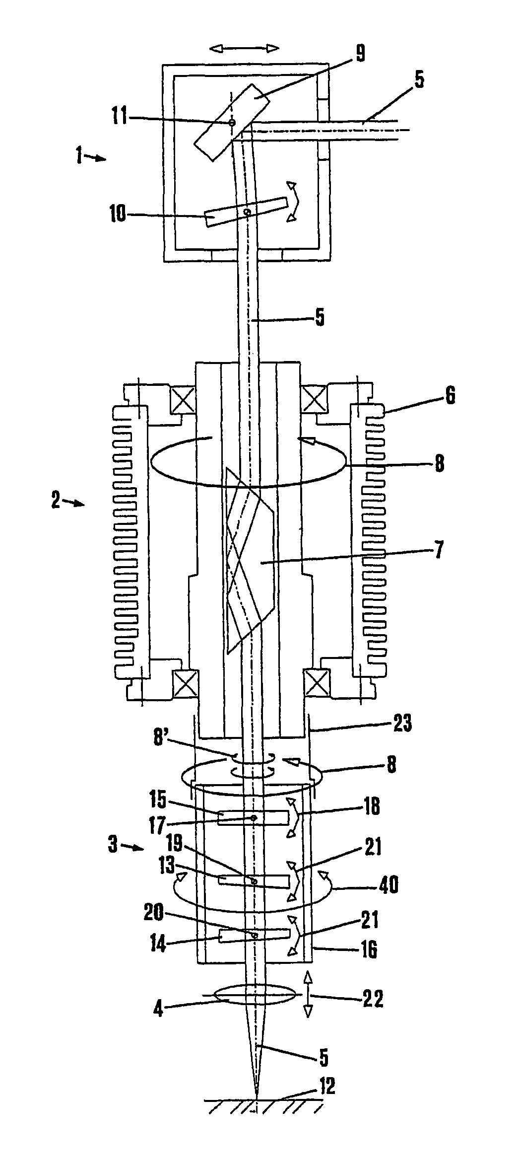
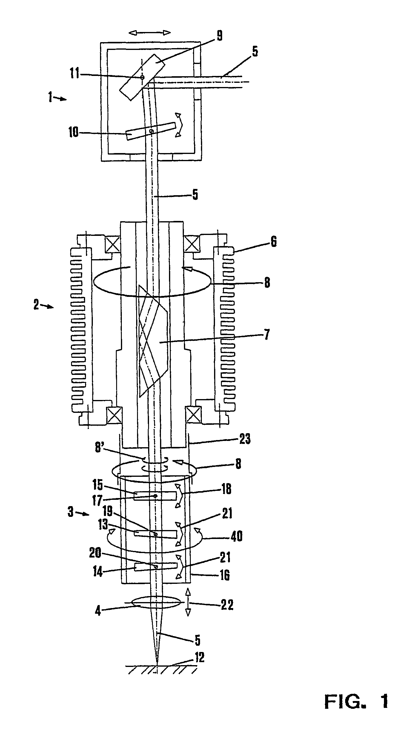
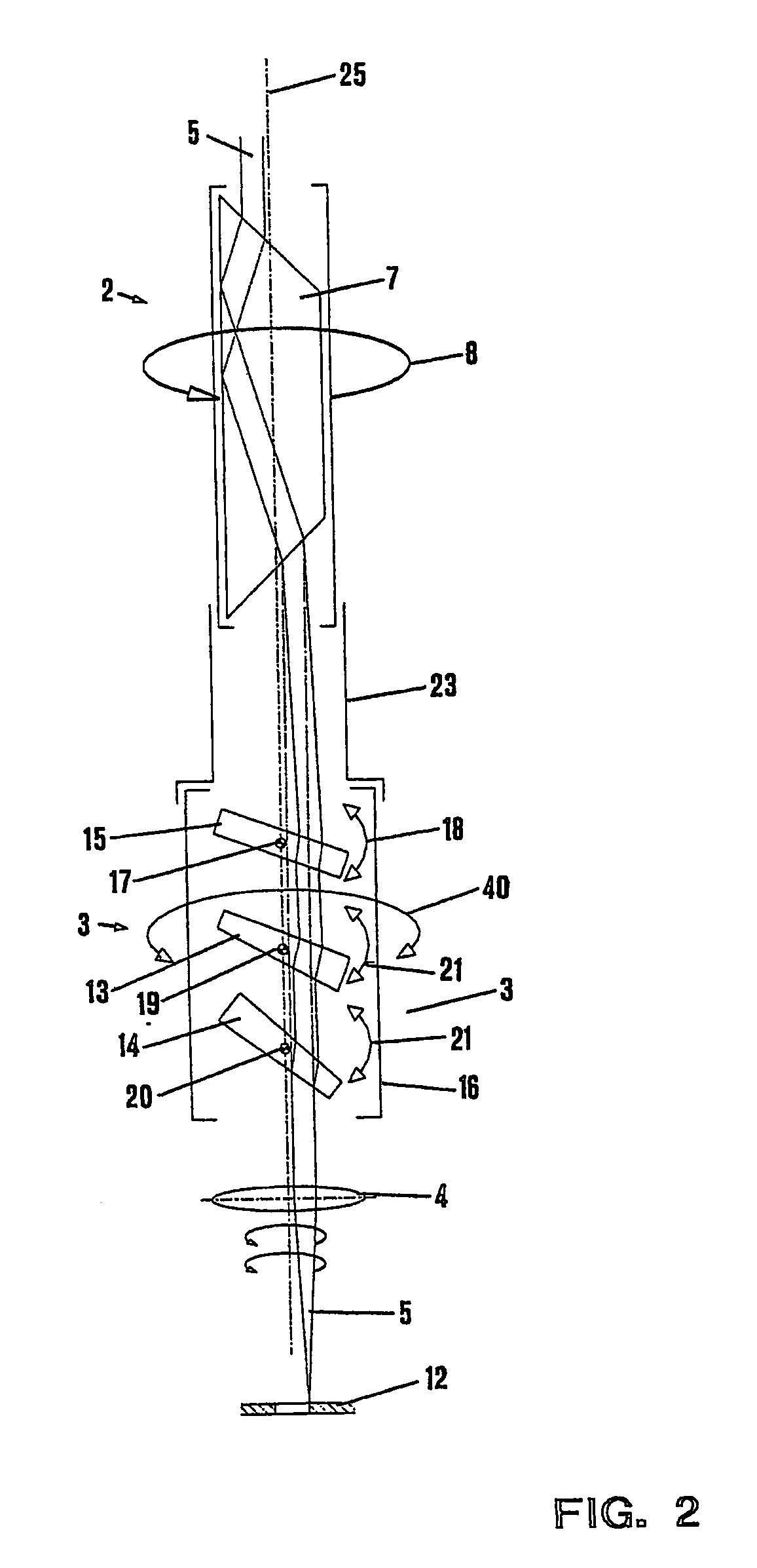
[0054]The device can be subdivided into a beam manipulator 1, an image rotator 2, a compensating device 3 and a focusing device 4, viewed in the direction of the extension of a laser beam, which is designated by reference numeral 5.

[0055]The image rotator 2, which is arranged in a rapidly rotating hollow-shaft motor 6 in the center thereof forms a drilling optic, wherein in the illustrated embodiment a Dove prism 7 is used as the image rotator 2. The Dove prism 7 is positioned in the hollow shaft motor 6 such that, when the image rotator 2 or the hollow shaft motor 6, respectively, is rotated once, as illustrated by the rotary arrow 8, the laser beam 5 pas...


PUM

PropertyMeasurementUnit
thicknessaaaaaaaaaa
thicknessaaaaaaaaaa
thicknessaaaaaaaaaa

Abstract

A device for drilling and for removing material using a laser beam comprises: a rotating image rotator (2); a beam manipulator (1) which, when viewed in the beam direction, is arranged in front of the image rotator and which serves to adjust the angle and position of the beam relative to the rotation axis of the image rotator; and a focusing device (3) located on the output side of the image rotator. A compensating device (3, 13, 14, 15) is placed between the image rotator and the focusing device and rotates with the image rotator in the same direction of rotation and with the same rotational frequency. The compensating device has a parallel displacement unit (15) and an angle changing unit (13, 14), and the compensating device, in a basic setting, is adjustable in its rotating position relative to the image rotator.

Description

BACKGROUND OF THE INVENTION[0001]The present invention relates to a device for drilling and for removing material using a laser beam, the device comprising a rotating image rotator, a beam manipulator which, when viewed in the beam direction, is arranged in front of the image rotator and which serves to adjust the angle and position of the beam relative to the rotation axis of the image rotator, and a focusing device located on the output side of the image rotator.[0002]In the car industry, in filtering technology, electronics and many other sectors, small bores or drilled holes are needed for very different applications. Examples are injection nozzles for fuels, in the case of which a large number of drilled holes or bores that are arranged in a definite way ensure a uniform distribution of fuel during the injection process, resulting in reduced fuel consumption. To achieve in this field, and also with other applications, a reproducible distribution that is as homogeneous as possib...

Claims


Application Information

Patent Timeline
Patent Type & Authority Patents(United States)
IPC IPC(8): B23K26/14B23K26/02
CPCB23K26/386G02B27/40G02B27/642B23K26/389
Inventor WAWERS, WELFGILLNER, ARNOLD
Owner FRAUNHOFER GESELLSCHAFT ZUR FOERDERUNG DER ANGEWANDTEN FORSCHUNG EV
Why Eureka
Try Eureka