Piston for Use in an Engine

Inactive Publication Date: 2016-02-25
DEERE & CO
View PDF2 Cites 0 Cited by
  • Summary
  • Abstract
  • Description
  • Claims
  • Application Information

AI Technical Summary

Benefits of technology

[0003]Disclosed is a piston having an outer surface and a bottom surface. The bottom surface comprises a convex region, a concave region, and a circumferential edge. The convex region is intersected by a longitudinal piston axis defined by the piston. The convex region is radially inward of and in contact with the concave region, the concave region is radially inward of an in contact with the circumferential edge, and the circumferential edge is radially inward of and in contact wit

Problems solved by technology

Such methods result in unwanted, unnecessary heat loss

Method used


Image

  • Piston for Use in an Engine
  • Piston for Use in an Engine
  • Piston for Use in an Engine

Examples


Example

[0009]Like reference numerals in the various drawings indicate like elements.

DETAILED DESCRIPTION OF THE DRAWINGS

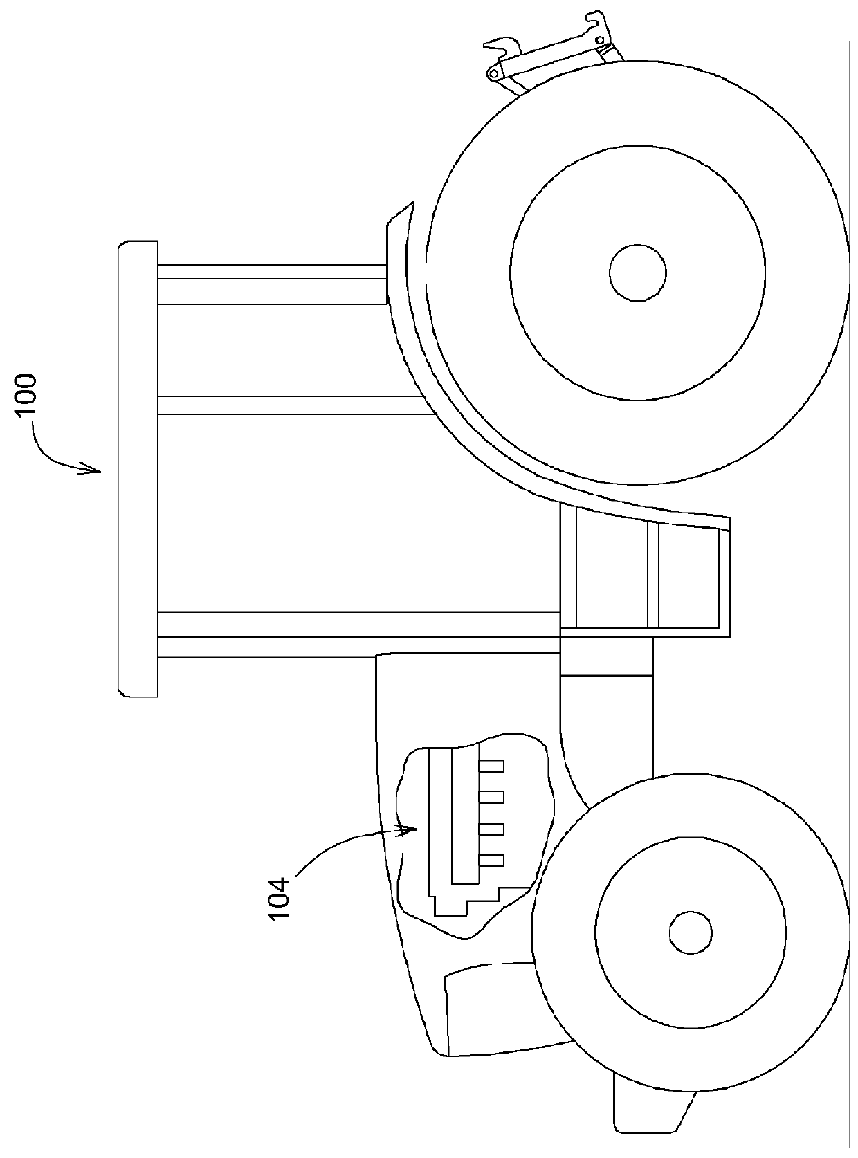
[0010]Referring to FIG. 1, there is shown an illustration of an engine 104 for providing power to a variety of machines, including on-highway trucks, construction vehicles, marine vessels, stationary generators, automobiles, agricultural vehicles, and recreational vehicles. In the illustrated embodiment, the machine 100 is an agricultural tractor. The engine 104 may be of any size, be of any configuration (e.g., “V,” inline, and radial), and have any number cylinders. The engine 104 may be a diesel engine.

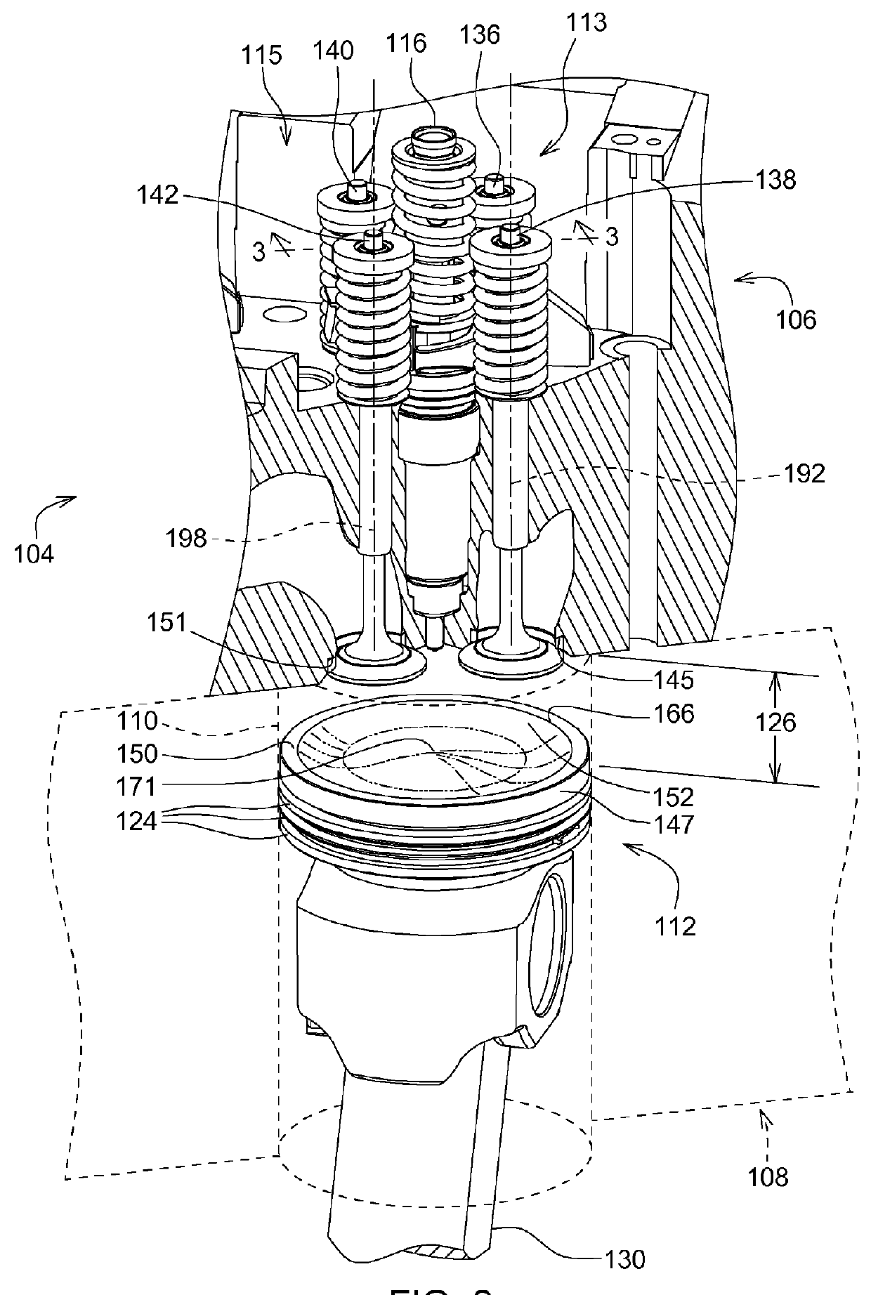
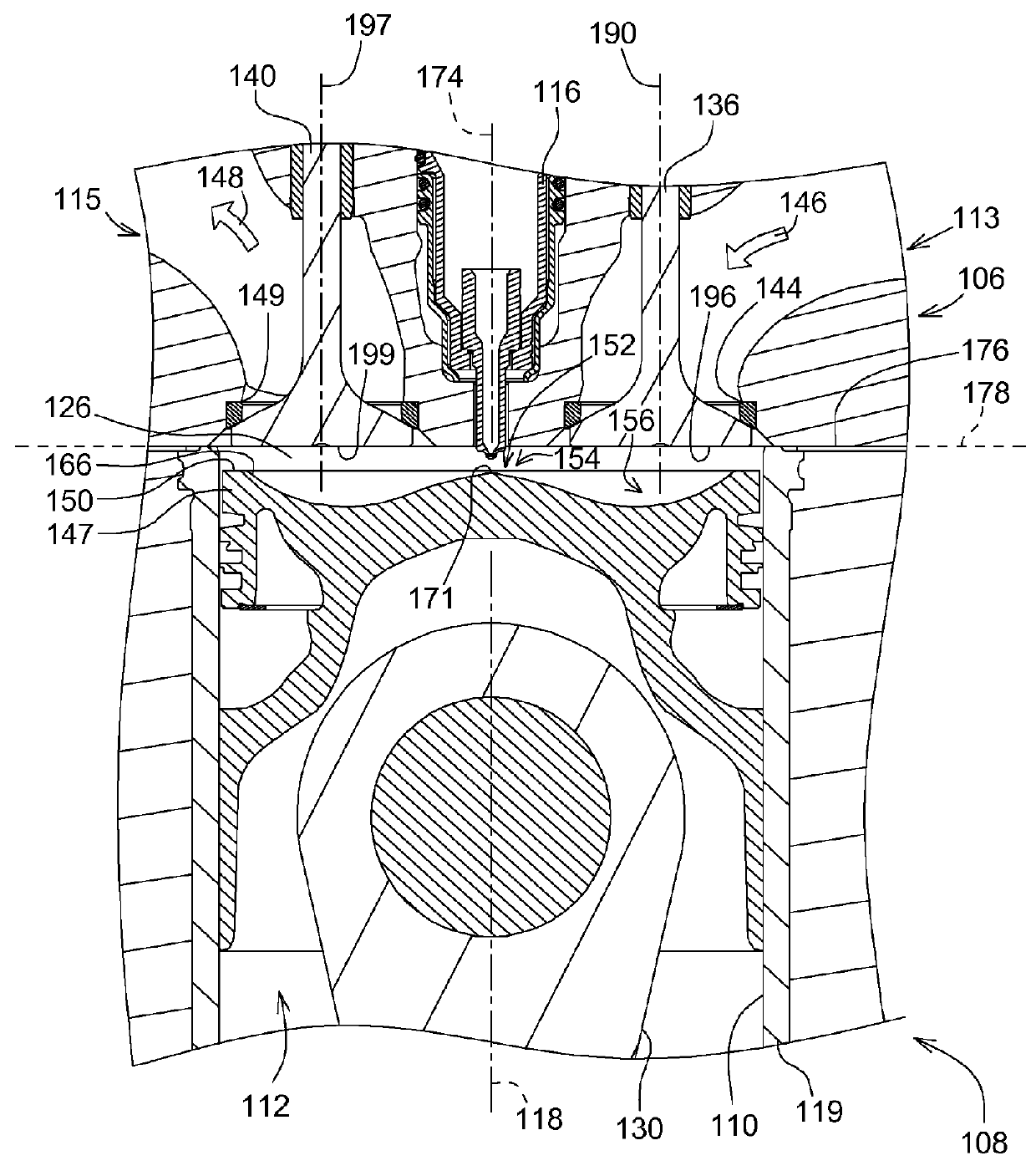
[0011]Next, referring to FIGS. 2 and 3, the engine 104 includes an engine block 108, a cylinder head 106, a combustion chamber 126, and a piston 112. The piston 112 is connected through a connecting rod 130 to a crankshaft of the engine 104. Combustion events cause the piston 112 to reciprocate along a rectilinear path within a cylinder 110, the cylinder 110 being partia...


PUM


Abstract

A piston having an outer surface and a bottom surface. The bottom surface comprises a convex region, a concave region, and a circumferential edge. The convex region is intersected by a longitudinal piston axis defined by the piston. The convex region is radially inward of and in contact with the concave region, the concave region is radially inward of an in contact with the circumferential edge, and the circumferential edge is radially inward of and in contact with the outer surface.

Description

FIELD OF THE DISCLOSURE[0001]The present disclosure relates to a piston for an engine.BACKGROUND OF THE DISCLOSURE[0002]An engine includes an engine block, a cylinder head, a combustion chamber, and a piston. The piston is connected through a connecting rod to a crankshaft of the engine. Combustion events, in the combustion chamber, cause the piston to reciprocate along a rectilinear path within a cylinder. The combustion chamber is formed at an end of the cylinder, and is bound at a first end by the cylinder head and at a second end by a top of the piston. Known engines utilize various methods for increasing the combustion rate of the fuel, including swirl, fuel impact on surfaces, and multiple injections, to name just a few examples. Such methods result in unwanted, unnecessary heat loss through the piston, the cylinder, and the cylinder head.SUMMARY OF THE DISCLOSURE[0003]Disclosed is a piston having an outer surface and a bottom surface. The bottom surface comprises a convex reg...

Claims


Application Information

Patent Timeline
IPC IPC(8): F02F3/24F02F1/24
CPCF02F1/24F02F3/24F02B23/0669F02B23/0696Y02T10/12
Inventor WINSOR, RICHARD E.CHO, NAM HYO
Owner DEERE & CO
Why Eureka
Try Eureka