Electrically drivable valve for controlling volumetric flows in a heating and/or cooling system of a motor vehicle

Active Publication Date: 2016-02-25
MAHLE INT GMBH
View PDF7 Cites 5 Cited by
  • Summary
  • Abstract
  • Description
  • Claims
  • Application Information

AI Technical Summary

Benefits of technology

[0009]It is therefore an object of the invention to provide an electrically

Problems solved by technology

High pressure losses arise here because of the redirection.
It is especially disadvantageous that the valve body in this design has three openings for two inlet ports and one outlet port; this results in a high sealing cost.
When the valve body moves, this has the result that the edges of the plurality of openings slide constantly over the seals a

Method used


Image

  • Electrically drivable valve for controlling volumetric flows in a heating and/or cooling system of a motor vehicle
  • Electrically drivable valve for controlling volumetric flows in a heating and/or cooling system of a motor vehicle
  • Electrically drivable valve for controlling volumetric flows in a heating and/or cooling system of a motor vehicle

Examples


Embodiment Construction

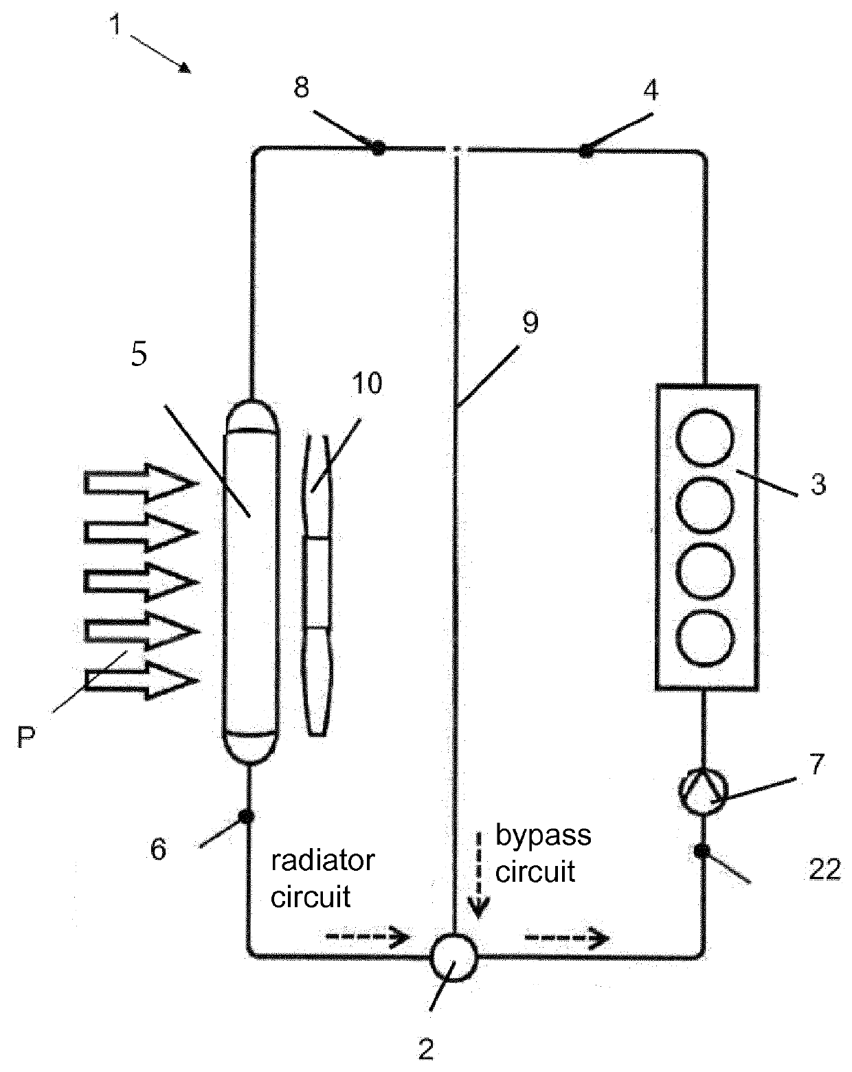
[0032]FIG. 1 shows a cooling circuit 1 of a motor vehicle with valve 2 of the invention as an ingress regulator. Cooling circuit 1 in this case has an internal combustion engine 3 whose engine outlet 4 is connected to a cooling element 5. Radiator return 6 is connected to valve 2. The outlet of valve 2 leads to intake side 22 of a pump 7, which in turn is connected to an internal combustion engine 3. A bypass or bypass circuit 9, which connects engine outlet 4 directly to valve 2 and thus again to pump 7 and internal combustion engine 3, is provided between engine outlet 4 and radiator inflow 8. Cooling element 5 is cooled by air (arrow P). A fan 10 is located behind cooling element 5.

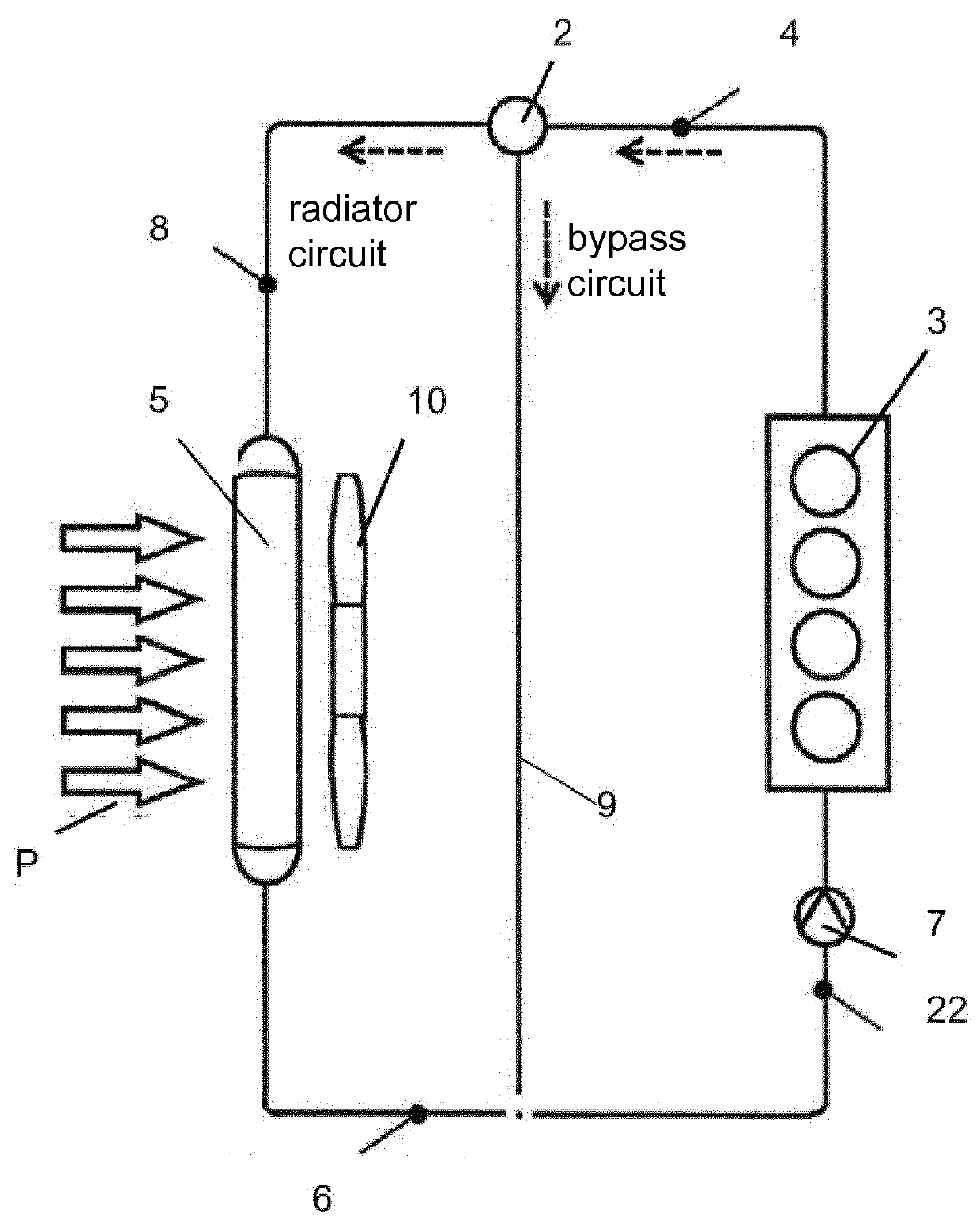
[0033]FIG. 2 differs from FIG. 1 only in that valve 2 functions as an egress regulator and is therefore connected between engine outlet 4 and radiator inflow 8. At the same time, valve 2 controls bypass circuit 9, which connects engine outlet 4 to intake side 22 of pump 7.

[0034]In the case of valve 2 f...


PUM


Abstract

An electrically drivable valve for controlling volumetric flows in a heating and/or cooling system of a motor vehicle, including a housing, from which at least two channels, preferable an inlet channel and an outlet channel, branch off, wherein a disk-shaped valve body is arranged in the housing, which valve body can be rotated about an axis of a drive shaft and has a control contour. For a valve that is simple to produce in regard to the design of the valve, the single control contour of the valve body controls a bypass circuit and a cooler circuit of the heating and/or cooling system.

Description

[0001]This nonprovisional application is a continuation of International Application No. PCT / EP2014 / 058383, which was filed on Apr. 24, 2014, and which claims priority to German Patent Application No. 10 2013 208 192.8, which was filed in Germany on May 3, 2013, and which are both herein incorporated by reference.BACKGROUND OF THE INVENTION[0002]1. Field of the Invention[0003]The invention relates to an electrically drivable valve for controlling volumetric flows in a heating and / or cooling system of a motor vehicle.[0004]2. Description of the Background Art[0005]Thermal management in cooling systems of motor vehicles is carried out today to reduce consumption, to reduce CO2 emissions, and to increase comfort. Depending on the thermal requirements, the coolant stoppage is realized in this case during warm-up, the coolant temperature of the internal combustion engine is controlled according to load conditions, and one or more auxiliary circuits such as the transmission fluid, engine ...

Claims


Application Information

Patent Timeline
IPC IPC(8): F16K31/02F16K11/074
CPCF16K11/074F16K31/02
Inventor KLEIN, HANS-PETERSTEURER, HANS-ULRICH
Owner MAHLE INT GMBH
Why Eureka
Try Eureka