Display Device and Television Receiver
a technology for television receivers and display devices, which is applied in the field of display devices and television receivers, can solve problems such as damage and difficulty in holding or fixing optical sheets
- Summary
- Abstract
- Description
- Claims
- Application Information
AI Technical Summary
Benefits of technology
Problems solved by technology
Method used
Image

Examples
embodiment 1
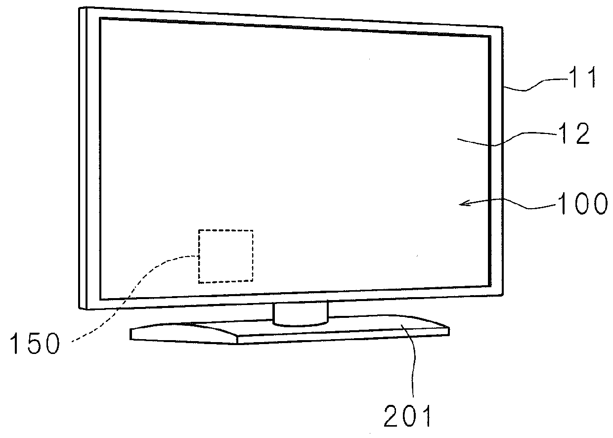
[0020]The present invention will be described below with reference to the drawings illustrating the embodiments thereof. FIG. 1 is a perspective view illustrating the exterior of one exemplified configuration of a television receiver 200 according to Embodiment 1. The television receiver 200 comprises a display device 100, a receiving part 150 which receives a television signal, a stand 201, and so forth. The display device 100 displays an image based on the television signal received by the receiving part 150. In addition, the display device 100 comprises a display panel 12 which is a rectangular liquid crystal panel and has one surface for a display surface, a bezel 11 covering the periphery of the display panel 12, and so forth. The details of the display device 100 will be described below.
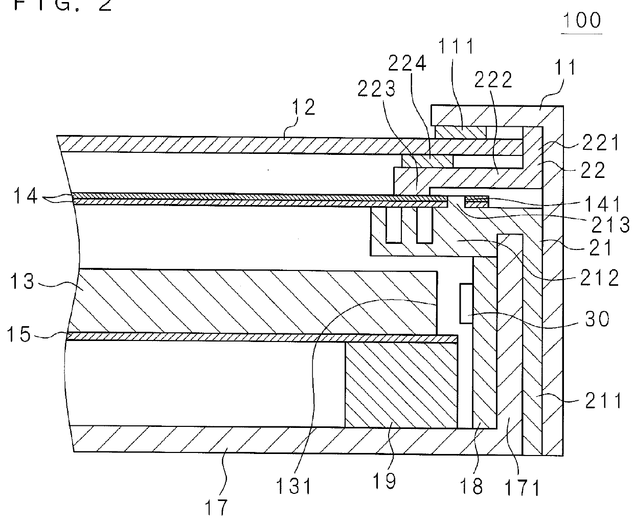
[0021]FIG. 2 is a cross-sectional view illustrating main components of the display device 100 according to Embodiment 1. As shown in FIG. 2, the display device 100 comprises the display panel 1...
embodiment 2
[0043]FIG. 4 is a cross-sectional view illustrating main components of a display device 110 according to Embodiment 2. While in Embodiment 1 it is configured that the protruding portion 213 is formed on the holding plate 212 as the first holding portion, it is different in Embodiment 2 that a protruding portion 225 is formed on the holding plate 222 as the second holding portion. It is noted that the same reference numerals denote the parts similar to those in Embodiment 1.
[0044]As shown in FIG. 4, in the holding plate 222, the protruding portion 225, as a locking portion which locks the optical sheet 14, is formed on the surface on which the optical sheet 14 is arranged. In addition, a hole 141, as a locked portion with which the protruding portion 225 is locked, is formed in the optical sheet 14.
[0045]Since the protruding portion 225 of the holding plate 222 locks the hole 141 of the optical sheet 14, the optical sheet 14 can be restricted to move and can be held securely. It is n...
embodiment 3
[0047]FIG. 5 is a cross-sectional view illustrating main components of a display device 120 according to Embodiment 3. While in Embodiments 1 and 2, the chassis 21 as the first holding portion and the chassis 22 as the second holding portion are separate members, a chassis 23 which is the unified one of the chassis 21 and 22 is provided in Embodiment 3. It is noted that the same reference numerals denote the parts similar to those in Embodiment 1.
[0048]As shown in FIG. 5, the unified chassis 23 has a holding plate 231 which holds the optical sheet 14 at the light guide plate 13 side, and a holding plate 232 which holds the optical sheet 14 at the side opposite to the holding plate 231. Therefore, the optical sheet 14 can be held securely.
[0049]By arranging the optical sheet 14 on the upper surface of the holding plate 231, the optical sheet 14 can be arranged in an appropriate space between the light guide plate 13 and the display panel 12, so that the bezel of the light source unit...
PUM
 Abstract
Description
Claims
Application Information
 - R&D
- Intellectual Property
- Life Sciences
- Materials
- Tech Scout
- Unparalleled Data Quality
- Higher Quality Content
- 60% Fewer Hallucinations
Browse by: Latest US Patents, China's latest patents, Technical Efficacy Thesaurus, Application Domain, Technology Topic, Popular Technical Reports.
© 2025 PatSnap. All rights reserved.Legal|Privacy policy|Modern Slavery Act Transparency Statement|Sitemap|About US| Contact US: help@patsnap.com