User-friendly jewelry chain

a jewelry chain and user-friendly technology, applied in the field of chain ornaments, can solve the problems of easy wear of screw threads, high assembly time and energy, and low productivity, and achieve the effects of convenient use, convenient assembly, and convenient assembly

Inactive Publication Date: 2016-03-03
NG PAK HEI
View PDF0 Cites 4 Cited by
  • Summary
  • Abstract
  • Description
  • Claims
  • Application Information

AI Technical Summary

Benefits of technology

[0003]An object of the present invention is to provide a user-friendly jewelry chain which is simple in structure, scientifically designed, capable of eliminating the need for alignment when mounting or adjusting the charms, convenient and quick to use, and equipped with a clasp with reliable positioning effect so that it will not be detached when worn.
[0011]As the present invention adopts the aforesaid technical proposal, it can achieve the following technical effects:
[0012](1) The present invention provides a flexible positioning component on the stop ring, and provides a positioning through-hole on the charm, so that when the charm is strung onto the chain, by pushing the charm and thereby compressing the flexible positioning component of the stop ring, the charm can pass through the stop ring and be strung onto the chain. Each of the charms is strung onto the chain accordingly. When a certain number of charms are strung onto the chain, one of the charms can be sleeved on the stop ring, so that the flexible positioning component on the stop ring can restore to its original state in the inner annular slot, thereby separating other charms. In the process of stringing, the charms of the present invention do not need to rotate several times like threads to pass the stop ring.
[0013]Besides, there is no need to provide positioning portions on the stop ring of the present invention to align with corresponding positioning portions of the charms when stringing the charms. Therefore, the present invention is more effective in assembling, more convenient in assembling, and more convenient to use. The flexible positioning component will not be worn out easily, thus having a longer lifespan.

Problems solved by technology

However, this method requires multiple rotations of the charms during assembly before the charms can pass through the stop ring, thus consuming much time and energy for assembly, and the productivity is low.
Screw threads are easily worn out while in use, reducing the lifespan of the jewelry chain.
This method requires the charm to be aligned with the stop ring for multiple times during assembly, thus assembly is inconvenient.
When in use, the positioning through-hole of the charm may accidentally align with the positioning portion of the stop ring so that the charm may pass through the stop ring on its own, thus user needs to pass the charm through the stop ring again, resulting in inconvenience in use.
First, the male end and the female end are not secured together securely and are easy to be detached.
Second, the structures of the male end and the female end are complicated and are not good for production.
Third, assembling and securing the male end and the female end involve a lot of steps, thus assembly is inconvenient.
In view of the aforesaid disadvantages now present in the prior art, it is very necessary to redevelop and redesign the clasp part of the jewelry chain.

Method used


Image

  • User-friendly jewelry chain
  • User-friendly jewelry chain
  • User-friendly jewelry chain

Examples


Embodiment Construction

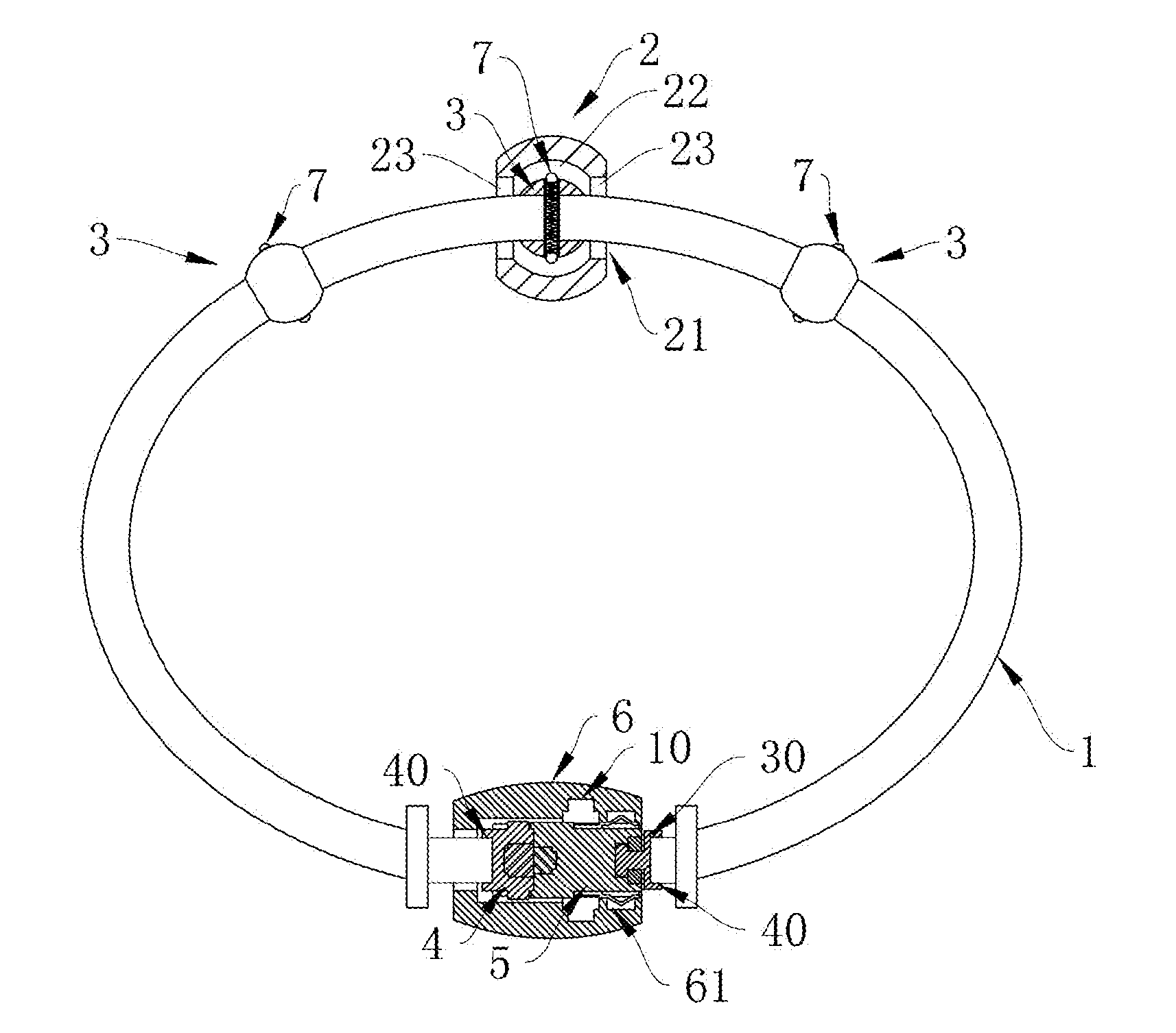
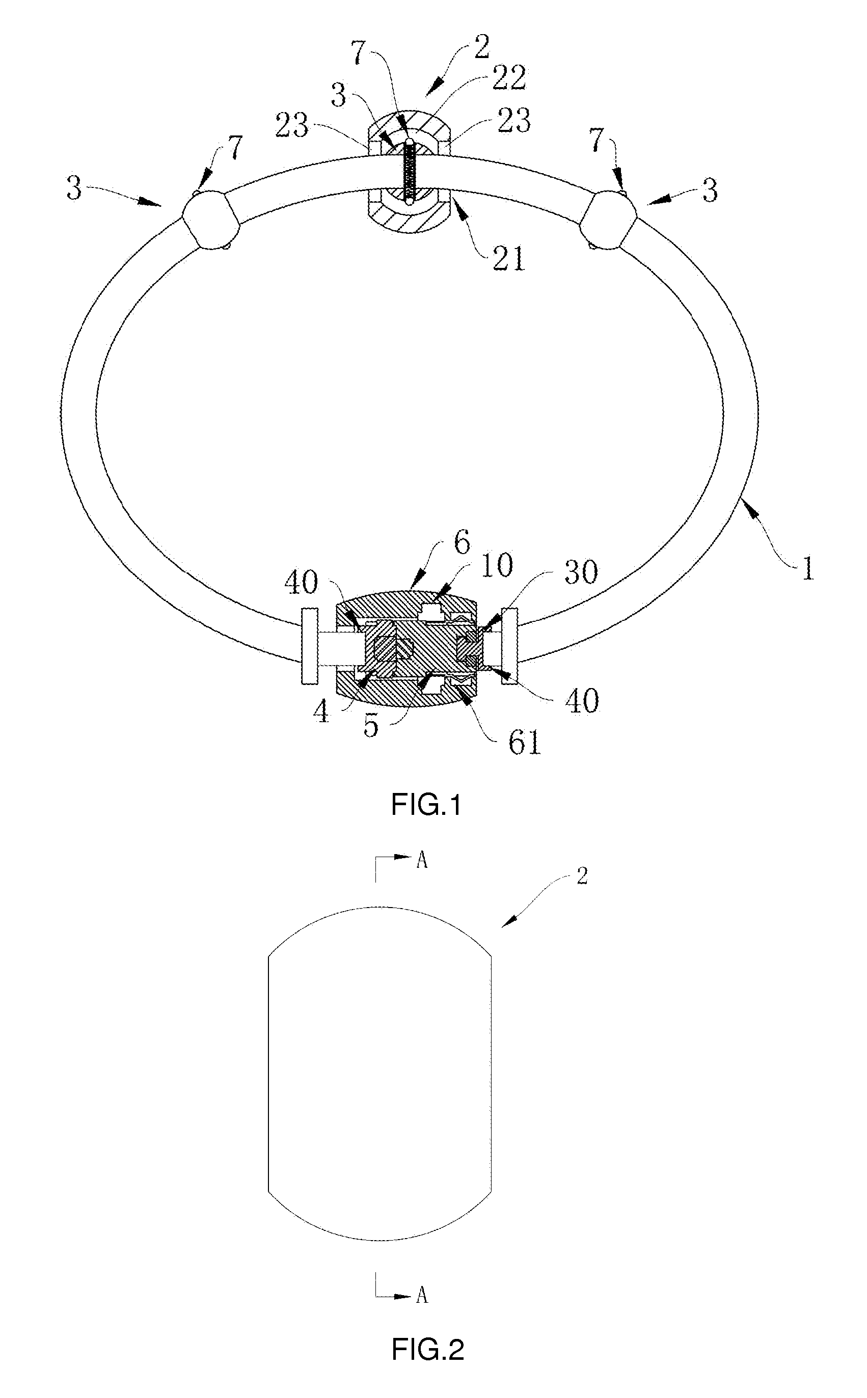
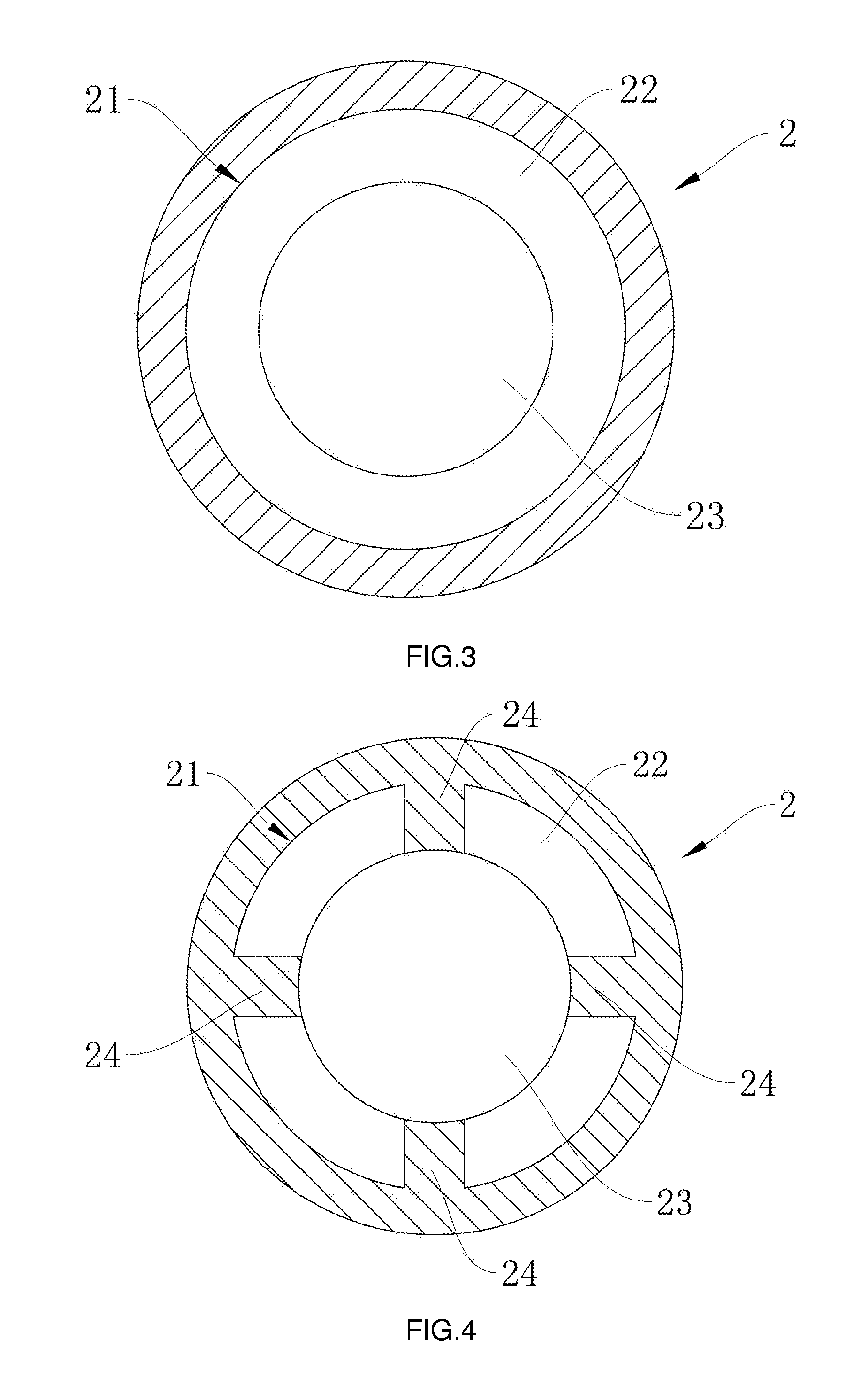
[0043]As shown in FIG. 1, the user-friendly jewelry chain of the present invention comprises a chain 1, at least one charm 2, at least one stop ring 3 which can be fixed on the chain 1 and a clasp. The stop ring 3 is provided with a flexible positioning component 7. As shown in FIGS. 8, 9 and 10, the centre of the end face of stop ring 3 is provided with or opened with a perforation 31. The perforation 31 is in a shape which allows the chain 1 to pass through, and the perforation 31 has a diameter slightly larger than the cross sectional diameter of the chain 1, so that the stop ring 3 can be easily and freely strung onto the chain 1. As shown in FIGS. 2 to 7, the charm 2 is provided with a positioning through-hole 21 which allows the chain 1 and the stop ring 3 to pass through. As shown in FIG. 1, the charm 2 is sleeved on the stop ring 3, and the charm 2 is fixedly positioned on the stop ring 3 by the flexible positioning component 7 acting on a hole wall of the positioning throug...


PUM


Abstract

A user-friendly jewelry chain having a chain, a charm, a stop ring and a clasp; the stop ring has a flexible positioning component; the charm has a positioning through-hole. The charm is sleeved on the stop ring and fixedly positioned on the stop ring. The clasp has a male end, a female end, a locking sleeve, a flexible pin component and a flat spring component. The female end is connected to the chain; the flexible pin component and the flat spring component are respectively mounted on the female end. A pin slot and a flat spring slot are formed in the locking sleeve. The pin slot has horizontal slots and a vertical slot. The female end is sleeved into the locking sleeve. The flexible pin component and flat spring component of the female end respectively act on slot walls of the vertical slot and the flat spring slot.

Description

BACKGROUND OF THE INVENTION[0001]The present invention relates to a chain ornament, particularly a jewelry chain ornament strung with charms.[0002]Jewelry chain product such as hand chain, necklace and so forth basically comprises a chain, charms strung onto the chain and a closed-loop clasp for securing two ends of the chain together. In order to allow the charms to be fairly distributed on the chain, a stop ring is generally used to separate the charms on the chain. There are two methods of separating the charms by means of the stop ring. One of the methods is providing an external screw thread on an outer surface of the stop ring and an internal screw thread in an assembly opening of each of the charms, and passing the charms through the stop ring and preventing the charms from passing the stop ring on their own by means of the external screw thread of the stop ring and the internal screw threads of the charms. However, this method requires multiple rotations of the charms during...

Claims


Application Information

Patent Timeline
Patent Type & Authority Applications(United States)
IPC IPC(8): A44C11/00A44C25/00
CPCA44C25/007A44C11/00A44C5/2076A44C11/002A44C5/0007A44C5/18
Inventor NG, PAK, HEI
Owner NG PAK HEI
Why Eureka
Try Eureka