Sound source-separating device and sound source -separating method

Active Publication Date: 2016-03-03
HONDA MOTOR CO LTD
View PDF4 Cites 71 Cited by
  • Summary
  • Abstract
  • Description
  • Claims
  • Application Information

AI Technical Summary

Benefits of technology

[0028]According to the configuration of above mentioned (8), speech recognition can be performed on the sound signal separated based on the sound source direction estimation result of at least one of the image signal and the sound s

Problems solved by technology

Accordingly, when the accuracy of sound source localization is lower

Method used


Image

  • Sound source-separating device and sound source -separating method
  • Sound source-separating device and sound source -separating method
  • Sound source-separating device and sound source -separating method

Examples


first embodiment

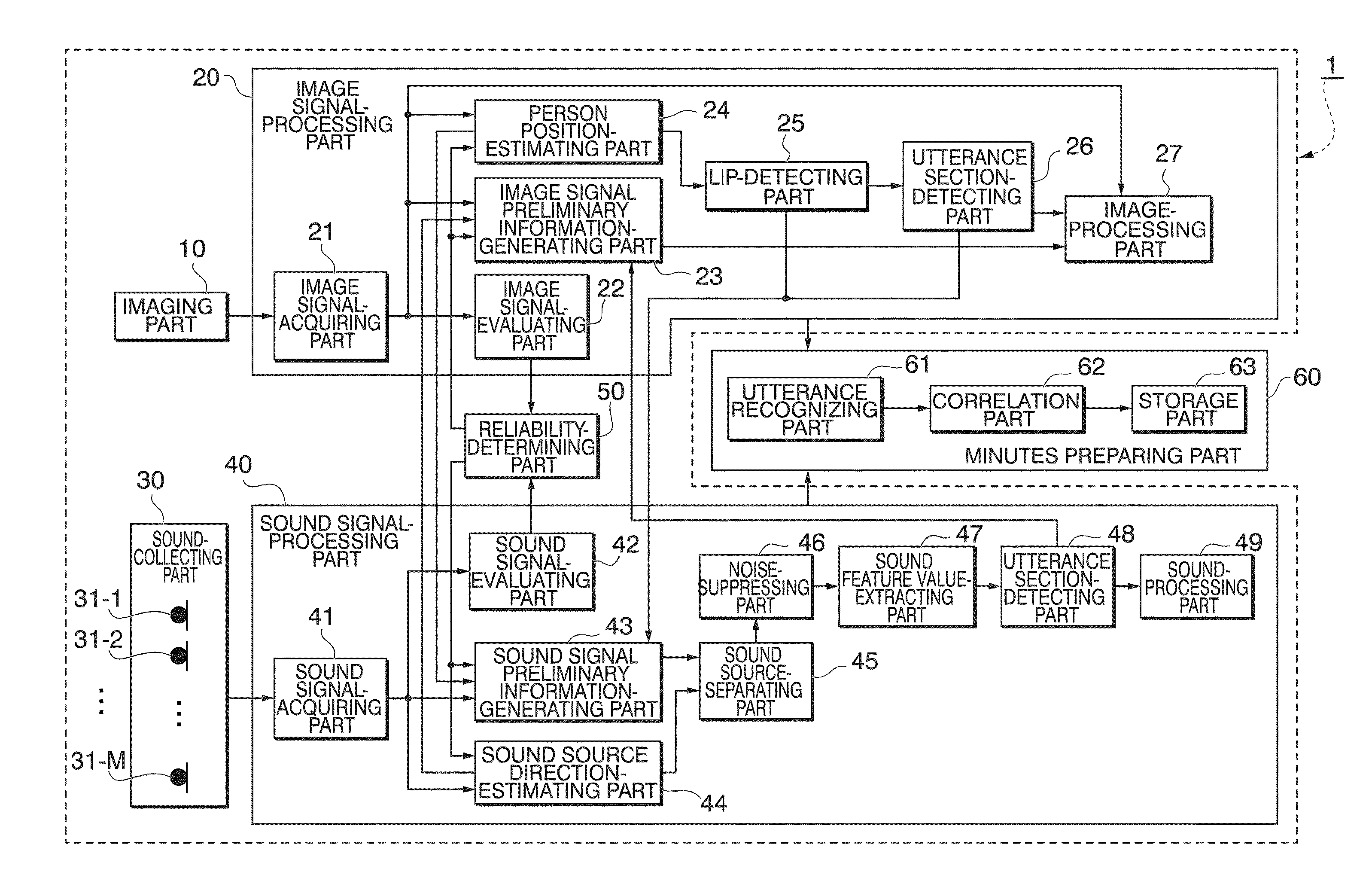
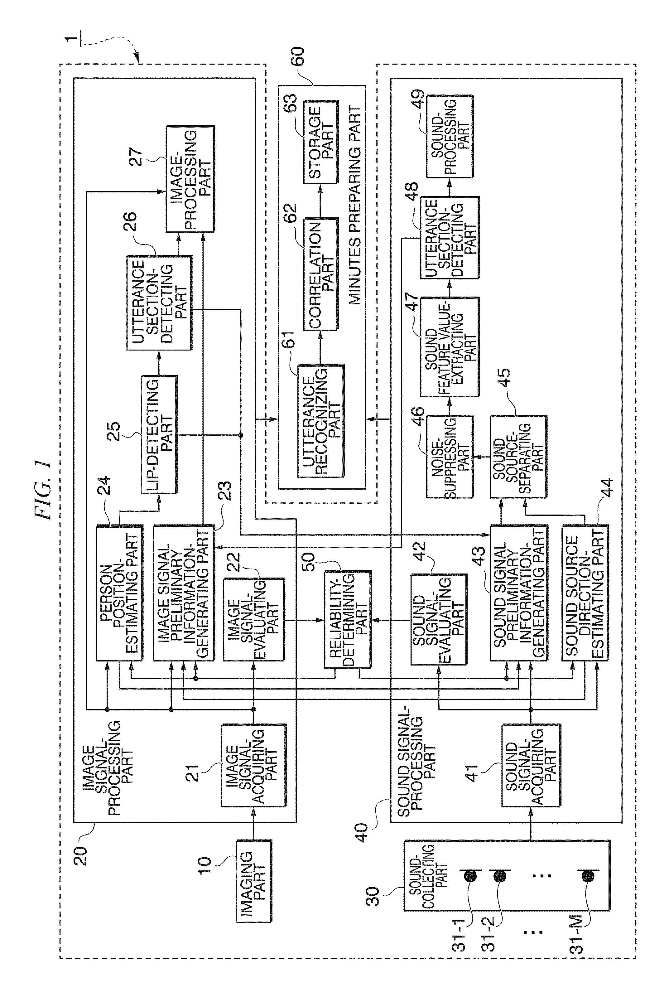
[0055]FIG. 1 is a block diagram illustrating a configuration of a sound source-separating device 1 according to a first embodiment of the present invention. As illustrated in FIG. 1, the sound source-separating device 1 includes an imaging part 10, an image signal-processing part 20, a sound-collecting part 30, a sound signal-processing part 40, and a reliability-determining part 50 (selection part). The sound source-separating device 1 is connected to a minutes preparing part 60. The sound source-separating device 1 may include the minutes preparing part 60.

[0056]The imaging part 10 captures an image at predetermined intervals and transmits an image signal generated by capturing an image to the image signal-processing part 20. The imaging part 10 may transmit the generated image signal in a wireless manner or a wired manner. When the number of imaging parts 10 is two or more, image signals only need to be synchronized with each other for each channel at the time of transmission. Th...

second embodiment

[0199]FIG. 20 is a block diagram illustrating a configuration of a sound source-separating device 1A according to a second embodiment. As illustrated in FIG. 20, the sound source-separating device 1A includes an imaging part 10, an image signal-processing part 20, a sound-collecting part 30, a sound signal-processing part 40, a reliability-determining part 50 (the selection part), and a transmission part 70. The sound source-separating device 1A is connected to a reception part 80 via a network 90. The network 90 may be a wired network or a wireless network. The reception part 80 is connected to a minutes preparing part 60. The functional parts having the same functions as in the sound source-separating device 1 (FIG. 1) according to the first embodiment will be referenced by the same reference marks and description thereof will not be repeated.

[0200]Image information subjected to the image processing and illustrated in FIG. 4 from the image signal-processing part 20 is input to the...


PUM


Abstract

A sound source-separating device includes a sound-collecting part, an imaging part, a sound signal-evaluating part, an image signal-evaluating part, a selection part that selects whether to estimate a sound source direction based on the first sound signal or the first image signal, a person position-estimating part that estimates a sound source direction using the first image signal, a sound source direction-estimating part that estimates a sound source direction, a sound source-separating part that extracts a second sound signal corresponding to the sound source direction from the first sound signal, an image-extracting part that extracts a second image signal of an area corresponding to the estimated sound source direction from the first image signal, and an image-combining part that changes a third image signal of an area other than the area for the second image signal and combines the third image signal with the second image signal.

Description

CROSS-REFERENCE TO RELATED APPLICATION[0001]Priority is claimed on Japanese Patent Application No. 2014-176518, filed on Aug. 29, 2014, the contents of which are incorporated herein by reference.BACKGROUND OF THE INVENTION[0002]1. Field of the Invention[0003]The present invention relates to a sound source-separating device and a sound source-separating method.[0004]2. Description of Related Art[0005]A device which collects the voice of participants in a conference and captures images of the participants has been proposed.[0006]For example, in a video teleconference, a video teleconference device is installed in each place in which the conference is held, the video teleconference devices are connected to each other via a network, and the video teleconference devices transmit the collected sound signals and captured image signals with each other.[0007]For example, Japanese Unexamined Patent Application, First Publication No. 2007-274462 proposes a video teleconference device including...

Claims


Application Information

Patent Timeline
IPC IPC(8): G10L17/02G06K9/00G06K9/46G06T7/00G10L15/26G10L25/84H04S7/00
CPCG10L17/02H04S7/302G10L25/84G06T2207/30201G06K9/4647G10L15/26G06K9/00261G06T7/0042G10L21/0208G10L21/0272G10L2021/02166G10L21/028H04R1/406H04R2430/23G06T7/73G06V40/167G06V40/171G06V10/507
Inventor MIZUMOTO, TAKESHINAKADAI, KAZUHIRO
Owner HONDA MOTOR CO LTD
Why Eureka
Try Eureka