Clamping device

a technology of a clamping device and a clamping plate, which is applied in the direction of clamps, vices, manufacturing tools, etc., can solve the problems of workpiece damage, inability to clamp workpieces of different shapes or sizes, and workpieces that cannot be held tight and are likely to loosen, so as to reduce the damage to the workpiece to be clamped, reduce the cost, and the effect of stably and easily clamping

Active Publication Date: 2016-03-10
9 SOLUTIONS TECH CO +1
View PDF9 Cites 20 Cited by
  • Summary
  • Abstract
  • Description
  • Claims
  • Application Information

AI Technical Summary

Benefits of technology

[0007]The present invention is aimed at providing a clamping device which has at least four clamping points to clamp the workpieces, and is capable of clamping differently sized and shaped workpieces with less damage.
[0011]Preferably, an elongated pin hole which is arranged in an inclined manner is formed at a left end of the jaw, two ends of the elongated pin hole are in the shape of a semicircle, and a pin hole is formed at a right end of the jaw, the two clamp pieces are provided with clamp-piece pin holes, the left and right ends of the jaw are connected to the clamp pieces by round pins, the round pin at the right end of the jaw is inserted in the elongated pin hole, so that the jaw is rotatable, and rotation of the jaw is restricted by relative displacement between the round pin and the elongated pin hole.
[0014]The advantages of the present invention are described as follow: the jaw is detachably connected between the two clamp pieces, the jaw is replaceable, which reduces the cost.
[0015]A lower edge of the jaw includes, in order from left to right, a first arc-shaped section, a second arc-shaped section and a horizontal section, so as to clamp different workpieces of different shapes. The bottoms of the first arc-shaped section, the second arc-shaped section and the horizontal section are at the same plane, so that the clamping device will have at least four clamping points when clamping a workpiece, which allows the workpiece to be clamped more stably and easily. The arc-shaped configuration of the first and second arc-shaped sections and can reduce damage to the workpiece to be clamped. The first and second arcs-shaped sections are symmetrical to each other, between the first and second arcs-shaped sections is defined an angle, and between the second arc-shaped section and the horizontal section is defined a V-shaped groove. The first and second arc-shaped sections are longer than the horizontal section. The angle and the V-shaped groove are used to clamp angular workpiece or small sized workpiece. Relatively large workpiece can be clamped between the first and second arc-shaped sections, and small workpieces can be clamped between the second arc-shaped section and the horizontal section. The second arc-shaped section and the horizontal section are provided with a toothed surface, which is an anti-skid design to increase friction of the jaw with respect to the workpiece. At the top end surface of the jaw are formed a ⅜ inch threaded hole and a ¼ inch threaded hole, so that some other workpieces or tools can be fixed to the jaw. Hence, the present invention requires less installation space, and is easy to set up or take down. An elongated pin hole which is arranged in an inclined manner is formed at a left end of the jaw, two ends of the elongated pin hole are in the shape of a semicircle, and a pin hole is formed at a right end of the jaw, the two clamp pieces are provided with clamp-piece pin holes, the left and right ends of the jaw are connected to the clamp pieces by round pins, the round pin at the right end of the jaw is inserted in the elongated pin hole, so that the jaw is rotatable, and rotation of the jaw is restricted by relative displacement between the round pin and the elongated pin hole. The jaw can be flexibly adjusted to clamp bigger workpiece. The clamping device of the present invention is reliable, easy to use, and capable of clamping different sized or shaped workpieces with less damage.

Problems solved by technology

There are various clamping devices currently available in the market, however, most of the clamping devices only have one or two clamping points to clamp the workpieces, so that the workpieces cannot be held tight and are likely to get loose.
Increasing the clamping force would cause damage to the workpiece.
Some clamping devices are specially designed in size and shape to fit the size and shape of a specific type of workpiece, and therefore are unable to clamp workpieces of different shapes or sizes.
For example, pipe-like workpieces must be clamped by arc-shaped clamping device, and angular workpieces can only be clamped by angular clamping device, which not only causes inconvenience but also increases cost.

Method used


Image

  • Clamping device
  • Clamping device
  • Clamping device

Examples


Embodiment Construction

[0018]The present invention will be clearer from the following description when viewed together with the accompanying drawings, which show, for purpose of illustrations only, the preferred embodiment in accordance with the present invention.

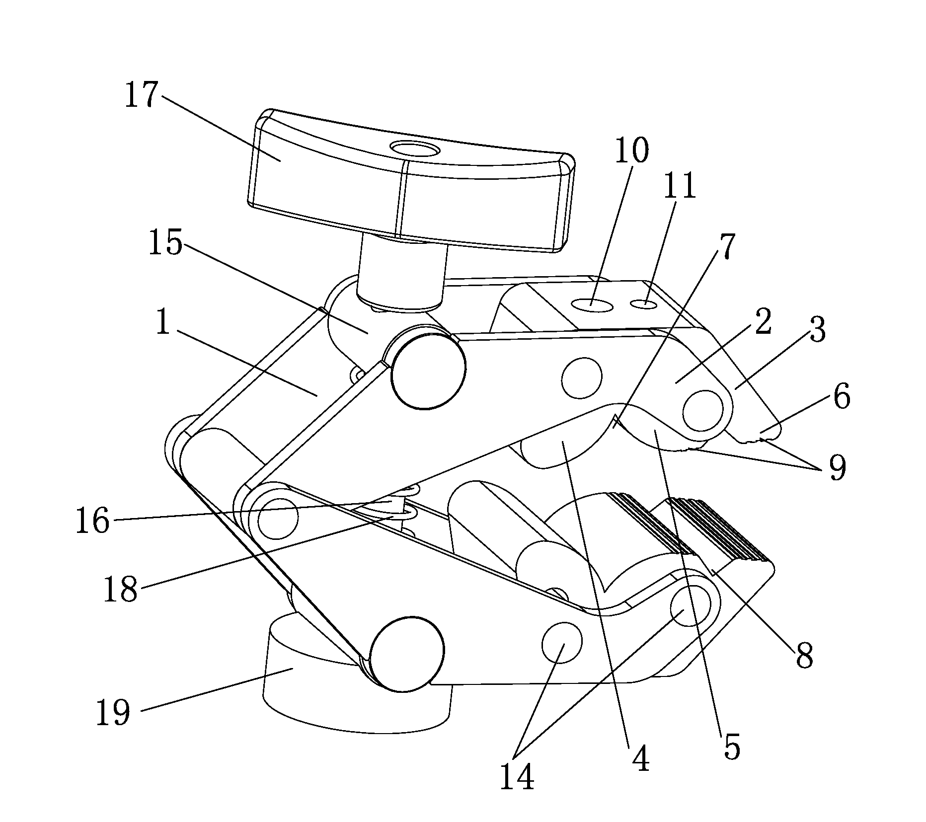
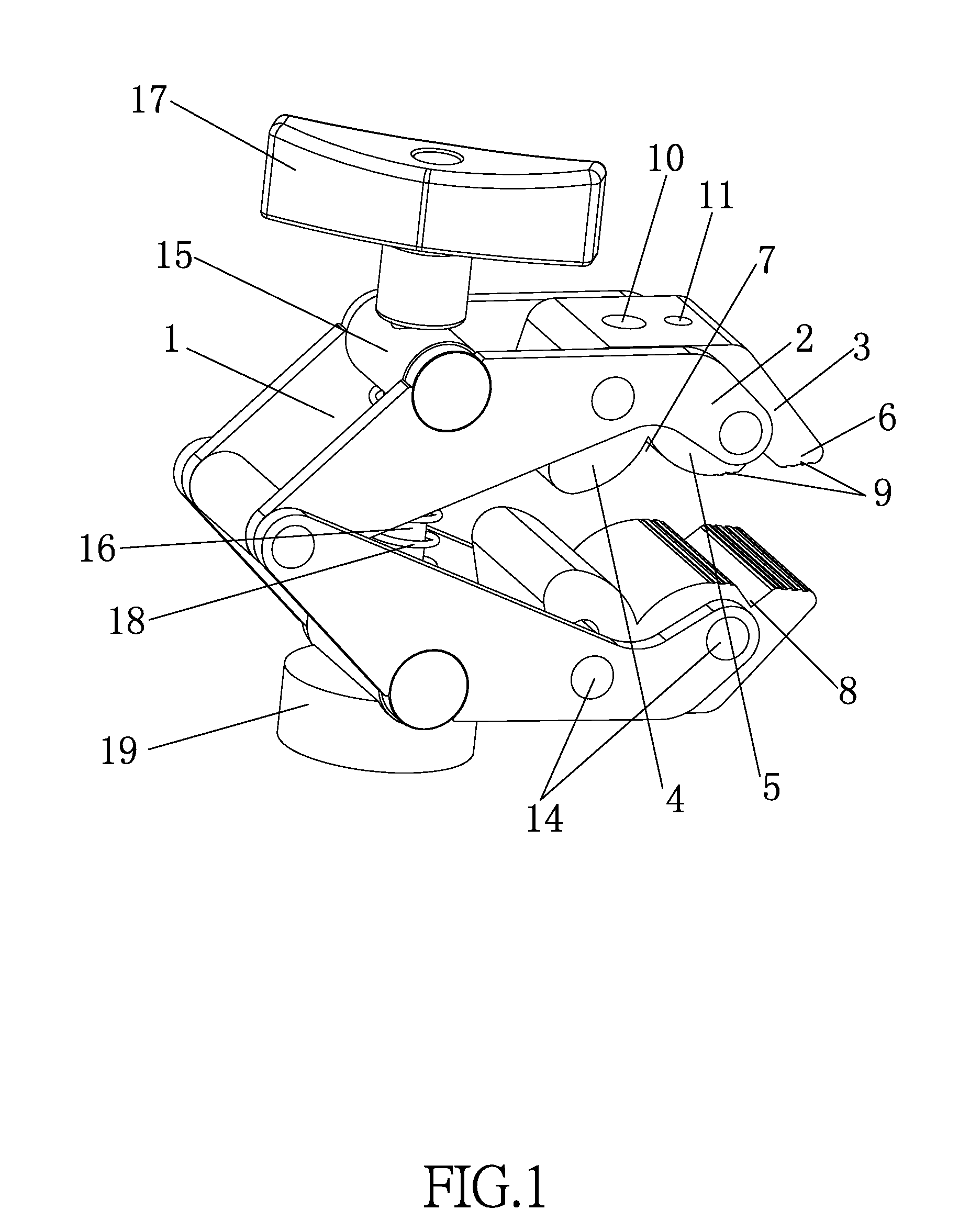
[0019]Referring to FIG. 1, a clamping device in accordance with a preferred embodiment of the present invention comprises a clamp assembly and an adjustment assembly. The clamp assembly comprises two symmetrical clamp arms 1 which are oppositely hinged to each other. The adjustment assembly is capable of adjusting the distance between the two clamp arms 1 to allow the clamping device to clamp workpieces of different sizes. The clamping device in accordance with the present embodiment is able to clamp workpieces of different shapes, such as round shape, arc shape, square shape, and angular shape.

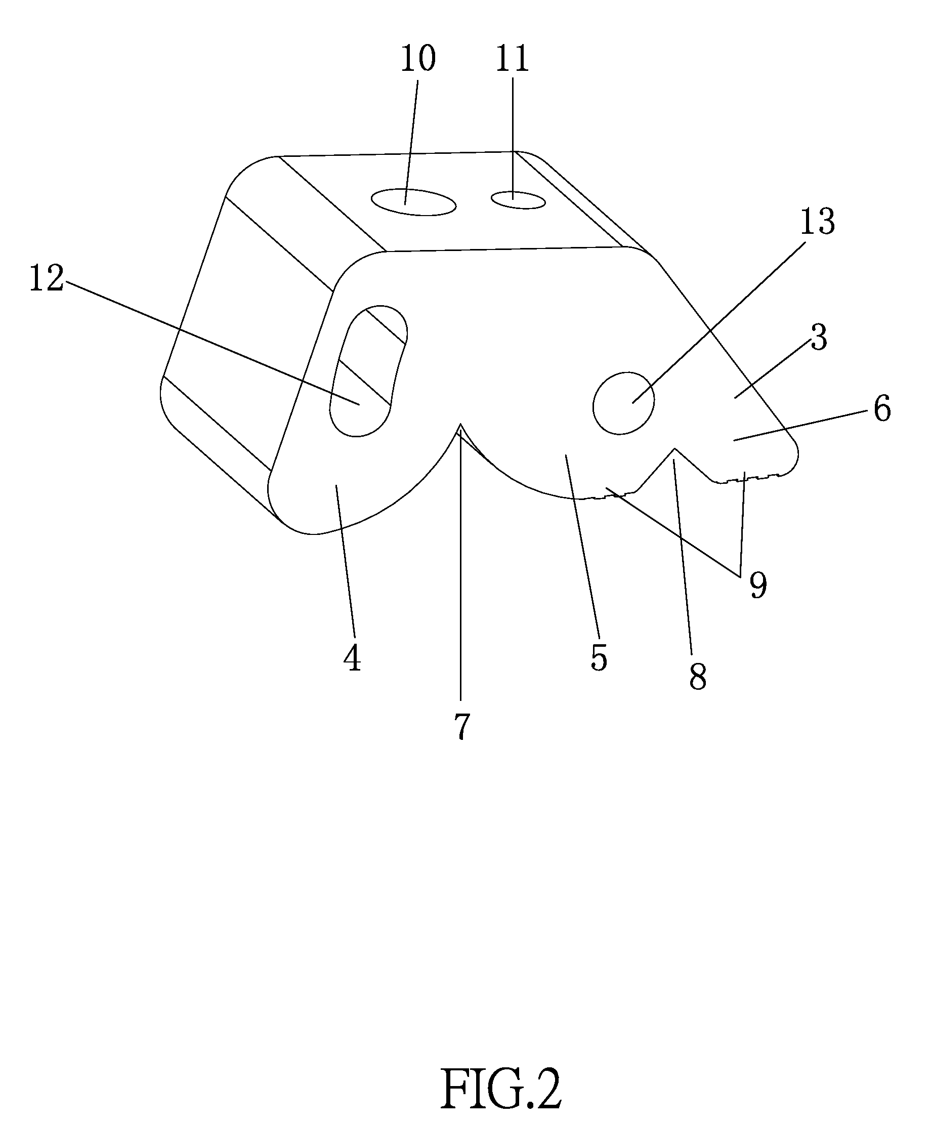
[0020]Since the clamp arms 1 are identical structures and for easy explanation, only one clamp arm 1 will be described in detail. The clamp arm 1 includes...


PUM


Abstract

A clamping device includes: a clamp assembly and an adjustment assembly, the clamp assembly comprises two symmetrical clamp arms which are oppositely hinged to each other. Each of the clamp arms includes two identical and parallel clamp pieces, and a jaw, the jaw is detachably connected between the two clamp pieces, a lower edge of the jaw includes, in order from left to right, a first arc-shaped section, a second arc-shaped section and a horizontal section, the bottoms of the first arc-shaped section, the second arc-shaped section and the horizontal section are at a same plane, the first and second arcs-shaped sections are symmetrical to each other, an angle is defined between the first and second arcs-shaped sections, a V-shaped groove is defined between the second arc-shaped section and the horizontal section, and the first and second arc-shaped sections are longer than the horizontal section.

Description

CROSS REFERENCE TO RELATED APPLICATION[0001]This application claims the benefit of priority to CN 201420517548.9, filed on Sep. 10, 2014 with the State Intellectual Property Office of the People's Republic of China, the entire specification of which is incorporated herein by reference.BACKGROUND OF THE INVENTION[0002]1. Field of the Invention[0003]The present invention relates to a clamping device.[0004]2. Related Prior Art[0005]Clamping devices are commonly seen in our daily life and bring much convenience to us, and are favored since they can clamp workpiece conveniently. There are various clamping devices currently available in the market, however, most of the clamping devices only have one or two clamping points to clamp the workpieces, so that the workpieces cannot be held tight and are likely to get loose. Increasing the clamping force would cause damage to the workpiece. Some clamping devices are specially designed in size and shape to fit the size and shape of a specific typ...

Claims


Application Information

Patent Timeline
Patent Type & Authority Applications(United States)
IPC IPC(8): B25B5/16B25B5/04B25B5/10
CPCB25B5/163B25B5/103B25B5/04
Inventor CHRISTENSEN, BO
Owner 9 SOLUTIONS TECH CO
Why Eureka
Try Eureka