Supercharge Your Innovation With Domain-Expert AI Agents!

Cast-in-place apparatuses for coupling objects to substrates and allowing movement of anchor members relative to substrates

a technology of substrates and casting apparatuses, which is applied in the direction of threaded fasteners, mechanical apparatus, nuts, etc., can solve the problems of large quantity of time, high cost, and inconvenient operation of conventional processes, and achieve the effect of facilitating the movement of an anchor member

Inactive Publication Date: 2016-03-10
ILLINOIS TOOL WORKS INC
View PDF5 Cites 12 Cited by
  • Summary
  • Abstract
  • Description
  • Claims
  • Application Information

AI Technical Summary

Benefits of technology

The invention allows for the movement of an anchor member in multiple directions or along multiple axes after it is cast into a substrate.

Problems solved by technology

During construction projects or other projects requiring anchoring, various aspects of the project may change that ultimately impact the desired or required location of the anchoring apparatus.
This conventional process is very time consuming and expensive.
Additionally, since the location of the conventional anchoring apparatuses must be extremely precise and any error in placement would result in demolishing the substrate, the individuals locating the anchoring apparatus in the substrate take a considerable amount of time to ensure accurate placement of the anchoring apparatuses.
This conventional manner of placing the anchoring apparatuses consumes a large quantity of time, thereby increasing labor costs and delaying the entire project.
Furthermore, humans are prone to error no matter the thoughtfulness and quantity of time utilized to ensure accuracy.
Thus, individuals installing anchoring apparatuses can still make mistakes when installing the anchoring apparatuses.
Such errors result in demolishing the substrate, repositioning the anchoring apparatuses and reforming the substrate around the anchoring apparatuses.

Method used


Image

  • Cast-in-place apparatuses for coupling objects to substrates and allowing movement of anchor members relative to substrates
  • Cast-in-place apparatuses for coupling objects to substrates and allowing movement of anchor members relative to substrates
  • Cast-in-place apparatuses for coupling objects to substrates and allowing movement of anchor members relative to substrates

Examples


Embodiment Construction

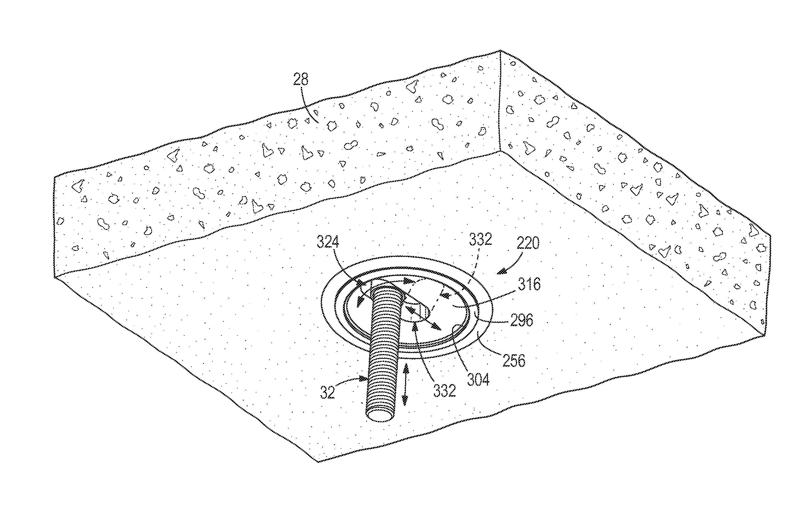
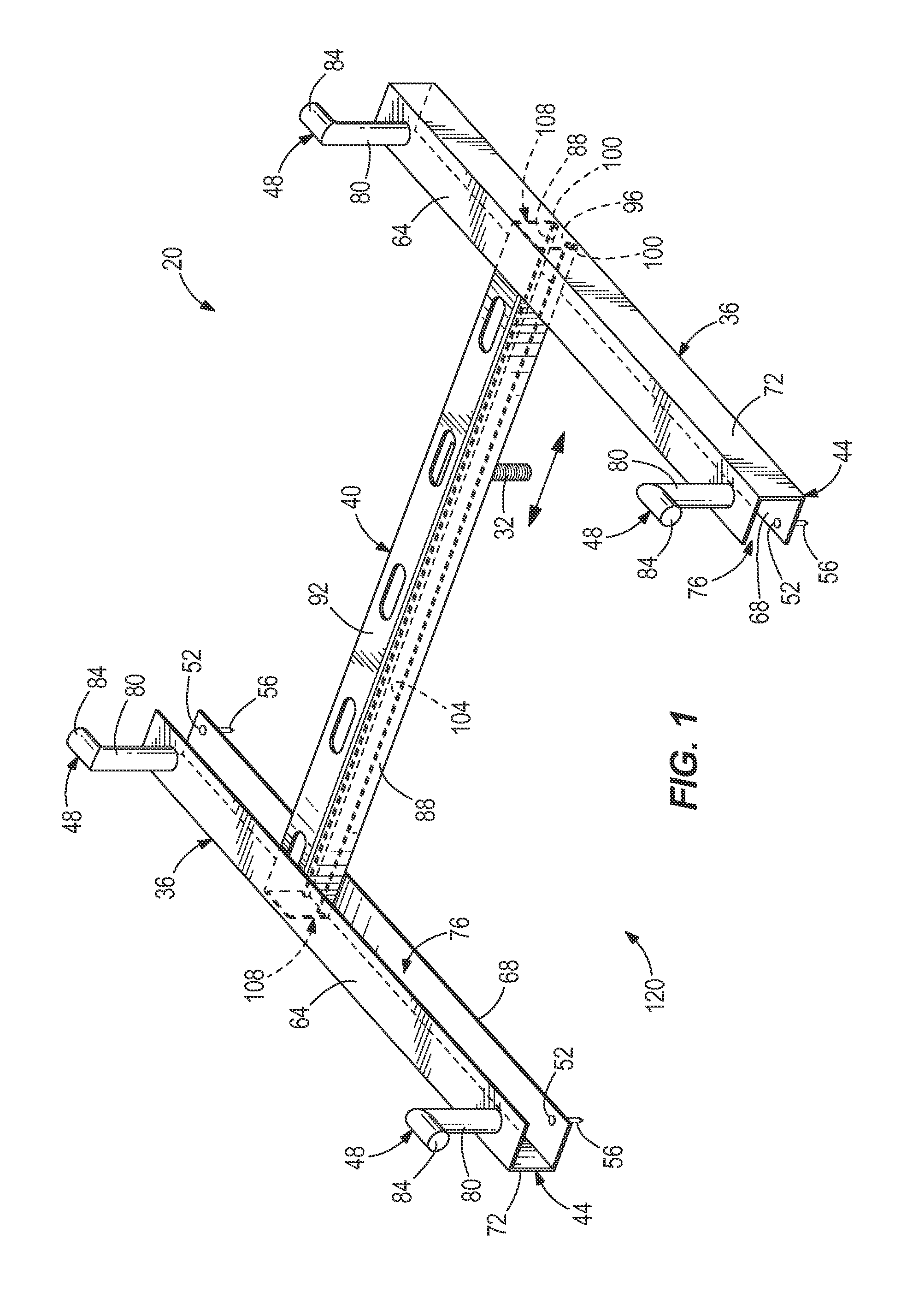
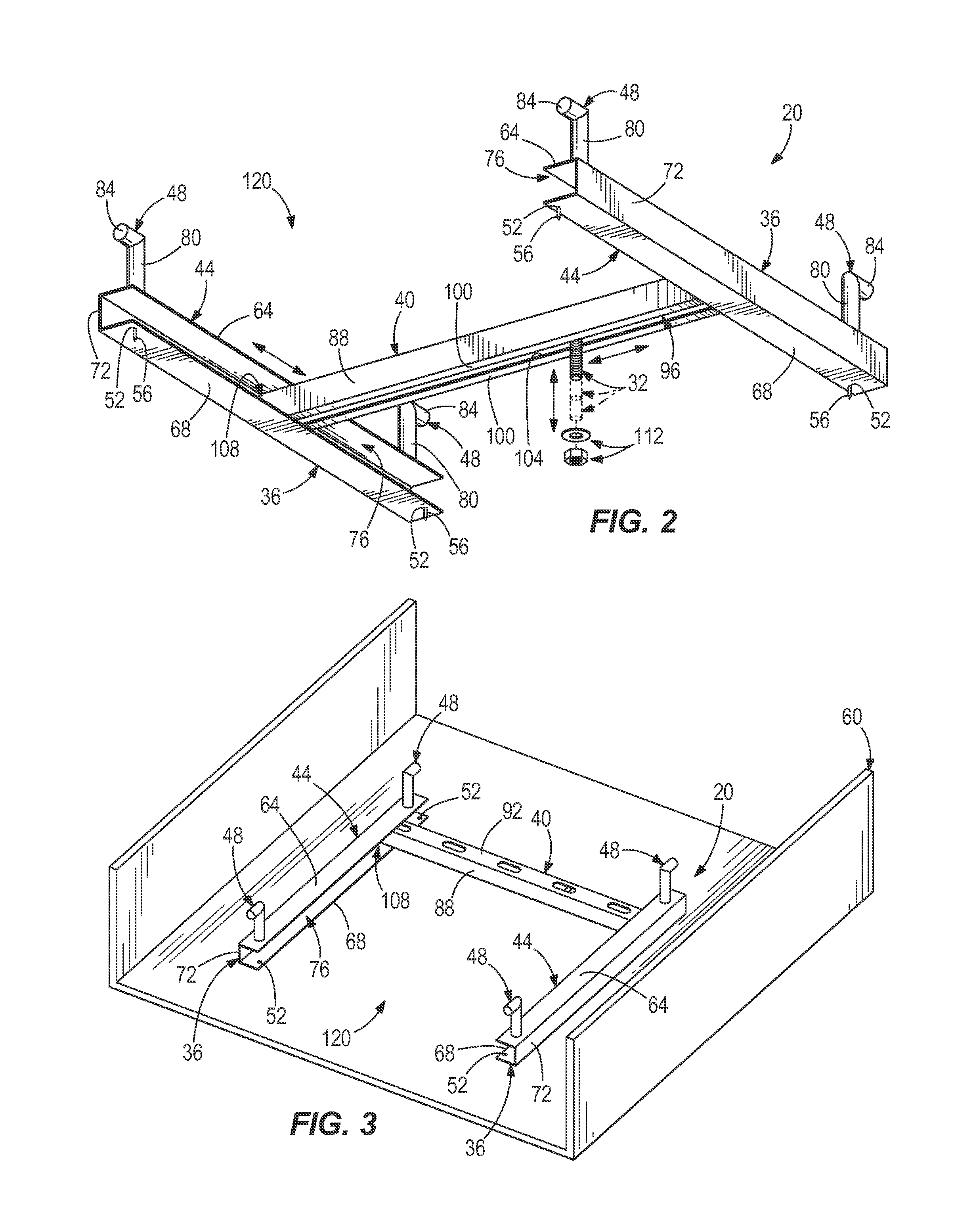
[0045]With reference to FIGS. 1-7, one example of an apparatus 20 for coupling an object 24 to a substrate 28 is illustrated. The apparatus 20 is configured to couple a wide variety of objects 24 to a wide variety of substrates 28. Examples of objects 24 include, but are not limited to, a duct, a conduit, electrical boxes or equipment, support members (e.g., pipe supports, etc.), rack structures, heavy equipment, secondary structural members, architectural members, among others. Examples of substrates 28 include, but are not limited to, concrete, asphalt, plastic, or other flowable materials capable of curing to a hard or rigid condition.

[0046]The apparatus 20 is capable of allowing movement or adjustability of an anchor member 32 in multiple directions or along multiple axes. In one example, the apparatus 20 allows movement of the anchor member 32 in two directions or along two axes (i.e., along any two of the x-axis, the y-axis and the z-axis in a three dimensional coordinate syst...


PUM


Abstract

In one aspect, a cast-in-place anchor apparatus is provided and includes a member configured to be cast into and unmovable relative to a substrate, and an anchor member coupled to and moveable relative to the member. The anchor member is configured to anchor an object relative to the substrate. In one aspect, the anchor member is moveable along two axes. In one aspect, the anchor member is moveable along three axes of a three-dimensional coordinate system.

Description

RELATED APPLICATIONS[0001]The present application claims the priority benefit of co-pending U.S. Provisional Patent Application No. 62 / 047,612, filed Sep. 8, 2014, which is incorporated by reference herein.FIELD OF THE INVENTION[0002]The present disclosure generally relates to apparatuses that may be cast into substrates and, more particularly, to apparatuses that may be cast into substrates for coupling objects to substrates.BACKGROUND[0003]Conventional manners of anchoring objects to substrates include anchoring apparatuses, such as a threaded fastener, cast into a substrate, such as concrete, by casting the apparatuses into the substrate. This conventional manner of anchoring fixes the anchoring apparatus in place upon curing of the substrate, thereby preventing manipulation of the anchoring apparatus along any axis. During construction projects or other projects requiring anchoring, various aspects of the project may change that ultimately impact the desired or required location...

Claims


Application Information

Patent Timeline
Patent Type & Authority Applications(United States)
IPC IPC(8): E04B1/41
CPCE04B1/4114E04B1/4157F16B5/0225F16B37/14F16B2200/99
Inventor CONNELL, ROBERT U.MCMATH, JUSTIN C.ERNST, RICHARD J.
Owner ILLINOIS TOOL WORKS INC
Features
  • R&D
  • Intellectual Property
  • Life Sciences
  • Materials
  • Tech Scout
  • Unparalleled Data Quality
  • Higher Quality Content
  • 60% Fewer Hallucinations
Learn More