Locking device

a technology of locking device and locking collar, which is applied in the direction of couplings, pipe elements, corrosion prevention, etc., can solve the problems of aircraft fuel filter system damage, serious manner, and aircraft damage, and achieve the effect of increasing the ease of use of locking collar and/or the speed of installation of locking collar, facilitating clip engagement, and increasing the resilience of the clip

Inactive Publication Date: 2016-03-10
AIRBUS OPERATIONS LTD
View PDF3 Cites 5 Cited by
  • Summary
  • Abstract
  • Description
  • Claims
  • Application Information

AI Technical Summary

Benefits of technology

[0010]The second engagement portion may comprise a resiliently deformable engagement surface. Providing a resiliently deformable engagement surface may allow use of the locking collar without requiring precise alignment of the fastener, the first pipe end, and second pipe end. This may increase the ease of use of the locking collar and / or the speed of installation of the locking collar. The resiliently deformable engagement surface may secure the locking collar in position, such that in normal use, the locking collar does not become disengaged from the fastener and the pipe end. The resiliently deformable engagement surface may comprise a metal or plastic clip. The clip may be housed in an aperture configured to be larger than the pipe end with which it is intended to be engaged, such that the clip and housing may be placed over the pipe end, and the clip engaged with the pipe end. The clip may be folded and / or crimped to increase the resilience of the clip and facilitate the engagement of the clip with the pipe end. There may be a plurality of clips provided. The clip may be any shaped protrusion suitable for engaging with a pipe end.
[0011]The first engagement portion may also comprise a resiliently deformable engagement surface. The resiliently deformable engagement surface may be as described with reference to the resiliently deformable engagement surface of the second engagement portion. Providing resiliently deformable engagement surfaces at both pipe engagement portions may provide an especially secure engagement with the pipe coupling.
[0012]The locking collar may comprise a one-piece device. Such a device may be moulded and / or machined. The locking collar may comprise a two piece device, such that the collar may be split prior to engagement with a pipe coupling, and then engaged together over the pipe coupling. The collar may be clamped or locked in position, in a “clam shell” type arrangement. This may provide an easy and quick way of installing the locking collar.
[0013]The locking collar may comprise a brightly coloured material. Providing a brightly coloured material may allow for easy visual checks to be performed during manufacture or maintenance procedures, for example checking that the locking collar is located correctly.

Problems solved by technology

Such leakage can damage the aircraft, possibly in a serious manner.
However, wire locking may result in fragments of wire entering the aircraft fuel filter system and causing damage.
Wire locking may also increase the complexity and / or installation and / or maintenance time when manufacturing or maintaining an aircraft.

Method used


Image

  • Locking device
  • Locking device
  • Locking device

Examples


Embodiment Construction

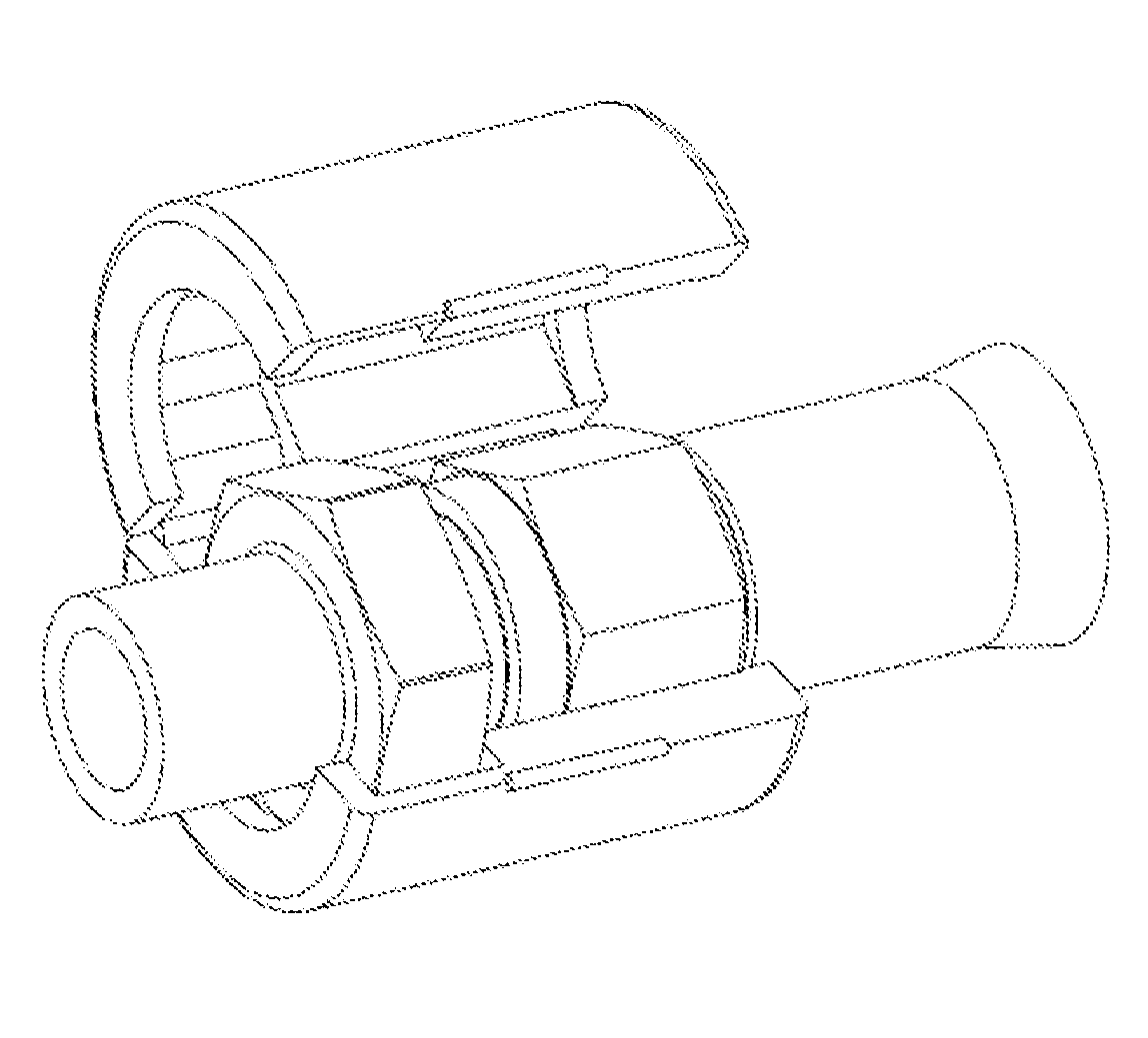
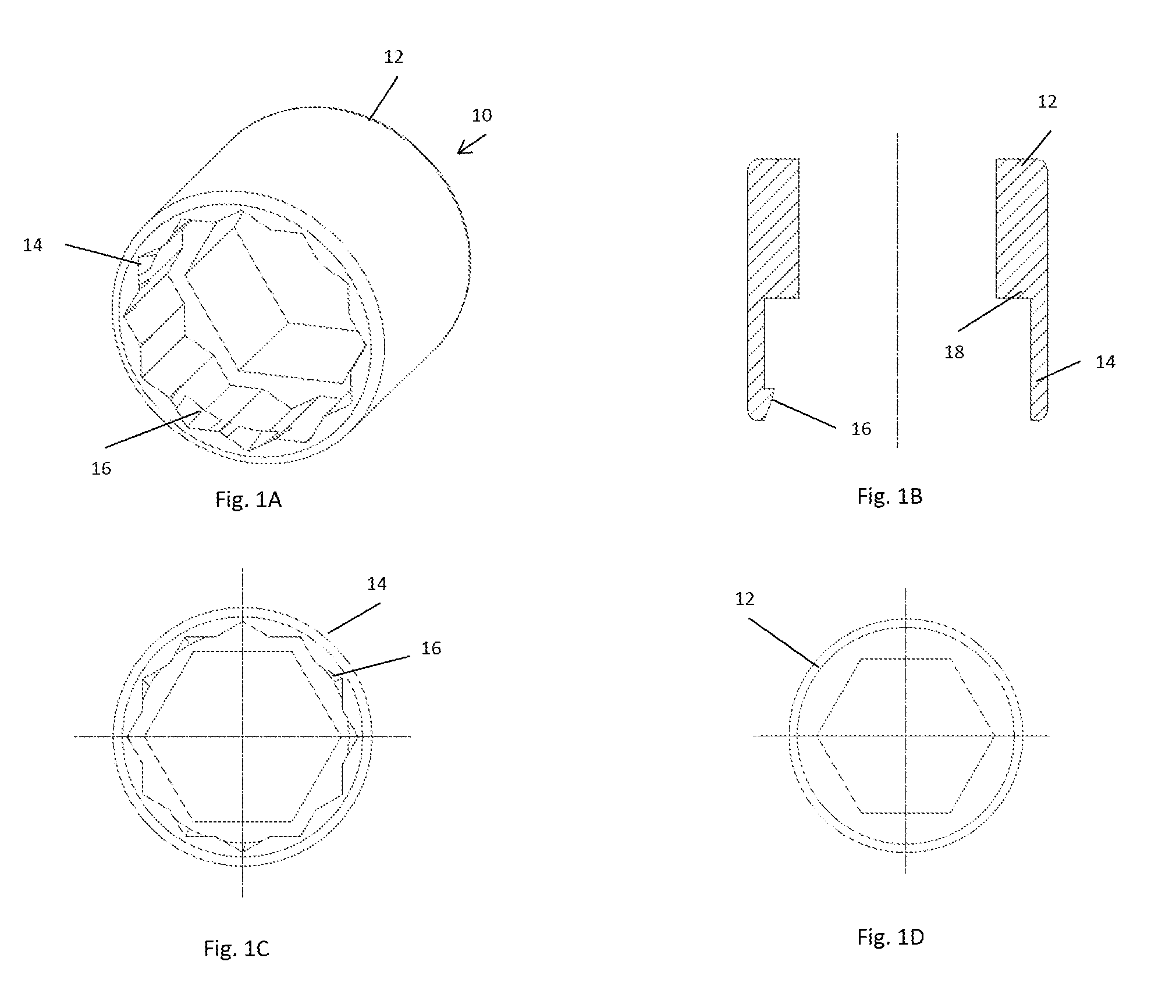
[0030]FIGS. 1A, 1B, 1C, and 1D, show a locking collar 10 according to a first embodiment of the invention. The locking collar 10 comprises a first engagement portion 12 and a second engagement portion 14. The first engagement portion 12 comprises an aperture shaped and sized to fit over and engage with a fastener, the fastener comprising a nut associated with a first pipe end. In this case, the aperture is hexagonal, which corresponds to the shape of the nut with which the first engagement portion 12 is intended to engage. The second engagement portion 14 comprises an aperture shaped and sized to fit over a pipe end, the pipe end comprising a nut. The second engagement portion also comprises a resiliently deformable engagement surface. The resiliently deformable engagement surface comprises a flexible clip 16 which is shaped and sized to fit over and engage with a second pipe end. The flexibility of the clip 16 allows the second engagement portion 14 to engage with a pipe end, even ...


PUM


Abstract

An aircraft pipe coupling includes a first pipe end and a second pipe end connected to each other by a fastener. A locking collar restricts the rotational movement of the first pipe end, the second pipe end, and the fastener with respect to one another. The locking collar includes a first engagement portion and a second engagement portion, one of the engagement portions includes a resiliently deformable engagement surface. The first engagement portion is located over and engaged with the fastener, and the second engagement portion is located over and engaged with the second pipe end.

Description

RELATED APPLICATION[0001]This application claims priority to United Kingdom (GB) patent application GB1415806.7, filed Sep. 8, 2014, the entirety of which is incorporated by reference.BACKGROUND OF THE INVENTION[0002]The present invention concerns an aircraft pipe joint. More particularly, but not exclusively, this invention concerns a locking device for an aircraft pipe joint. The invention also concerns a locking device for an aircraft fuel pipe joint.[0003]Aircraft pipe joints, for example in aircraft fuel systems, often include a washer disposed between a first pipe end and a second pipe end. The first pipe end and second pipe end are typically connected with at least one nut disposed on the outer surface of either the first pipe end or second pipe end. For aircraft pipe joints, especially in aircraft fuel systems, it is essential that there is no leakage from the pipe joint into the surrounding environment. Such leakage can damage the aircraft, possibly in a serious manner. Pip...

Claims


Application Information

Patent Timeline
Patent Type & Authority Applications(United States)
IPC IPC(8): F16L58/18F16L15/08F16L57/02
CPCF16L58/182F16L2201/40F16L57/02F16L15/08F16L19/005B64C1/1453B64D37/005
Inventor WOLLASTON, TIMOTHYEVANS, SAMUEL
Owner AIRBUS OPERATIONS LTD
Why Eureka
Try Eureka