
Modular wall paneling system

a module and wall panel technology, applied in the direction of fluid tightness measurement, instruments, containers, etc., can solve the problems of difficult opening of packaging for legitimate customers, difficult cutting through clear packaging, and huge theft of various products within the stor

Active Publication Date: 2016-03-24
MARTINO MARC G
View PDF29 Cites 9 Cited by
  • Summary
  • Abstract
  • Description
  • Claims
  • Application Information

AI Technical Summary

Benefits of technology

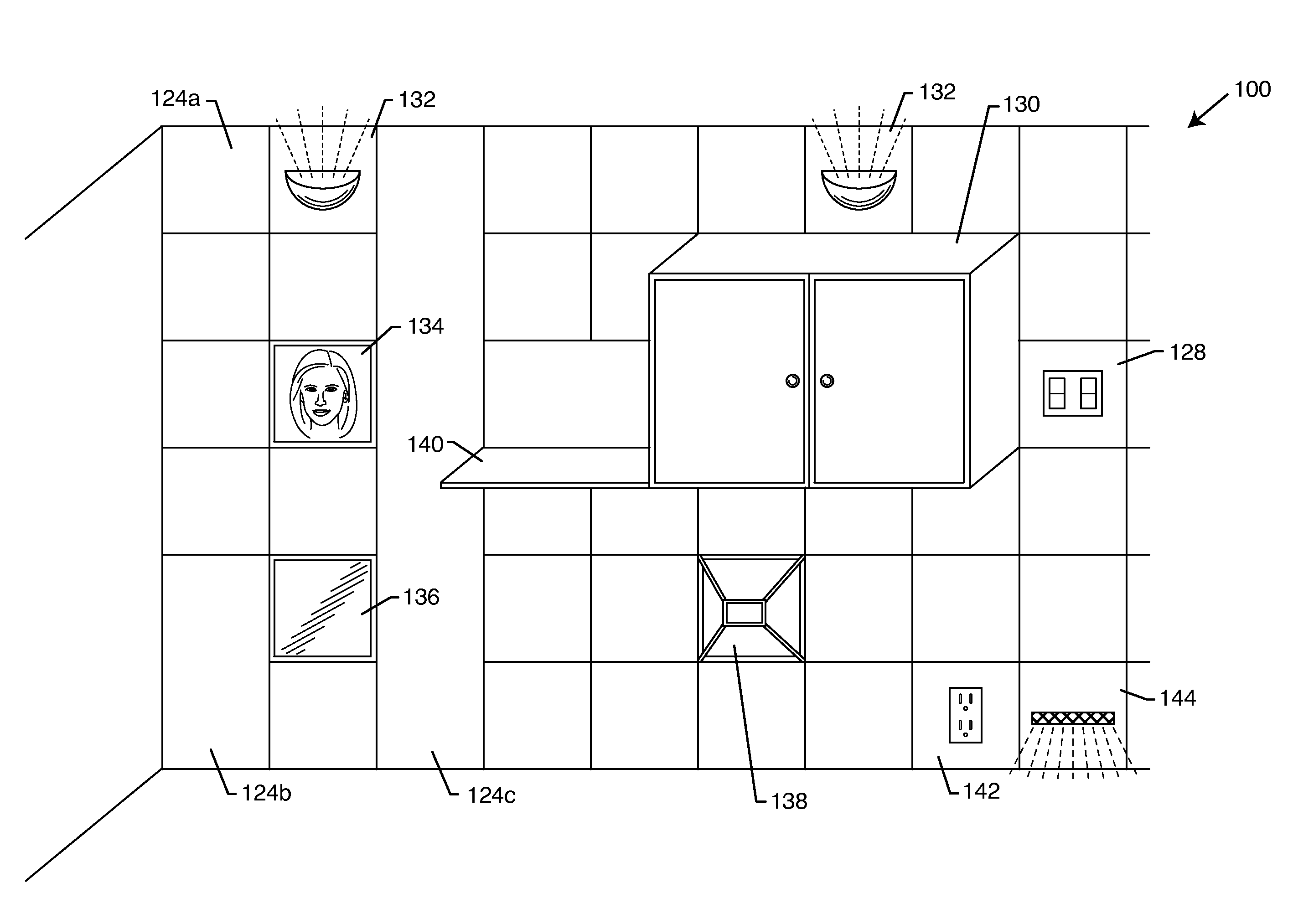
This patent describes a modular wall paneling system that includes plates and panels that can be easily joined together. The plates have fixture apertures and panel apertures that make it easy to attach the panels to the plates. The panels can have various functions such as being electronic switch panels, light switch panels, cabinet panels, or others. The plates can have angled bends or formed from a single flat piece of metal with bending processes. The panels have tabs that make it easy to install. Overall, the system provides a flexible and customizable solution for wall paneling.

Problems solved by technology

Theft of various products from within a store is a huge problem.
A thief will literally cut a product out of the clear plastic packaging and steal the product after discarding the packaging.
The prior art has focuses at making cutting through the clear packaging more difficult such that it is a deterrent to a potential thief.
However, adding a deterrent also makes the packaging harder to open for a legitimate customer.
Also, various deterrents can appear ugly and deter a customer from purchasing the product.
A problem exists when a resident wants to install shelving or other various features into a dry walled wall.
However, drywall is not nearly as strong as screwing directly into the studs of the home.
Many times during shelving installation the drywall is damaged or destroyed.
This may occur from missing the studs when attempting to screw therein, marring the drywall with improper screws, having screws become jammed or having the threads on the screw head strip.
Damage is also likely when electrical features are installed.

Method used


Image

  • Modular wall paneling system
  • Modular wall paneling system
  • Modular wall paneling system

Examples


Embodiment Construction

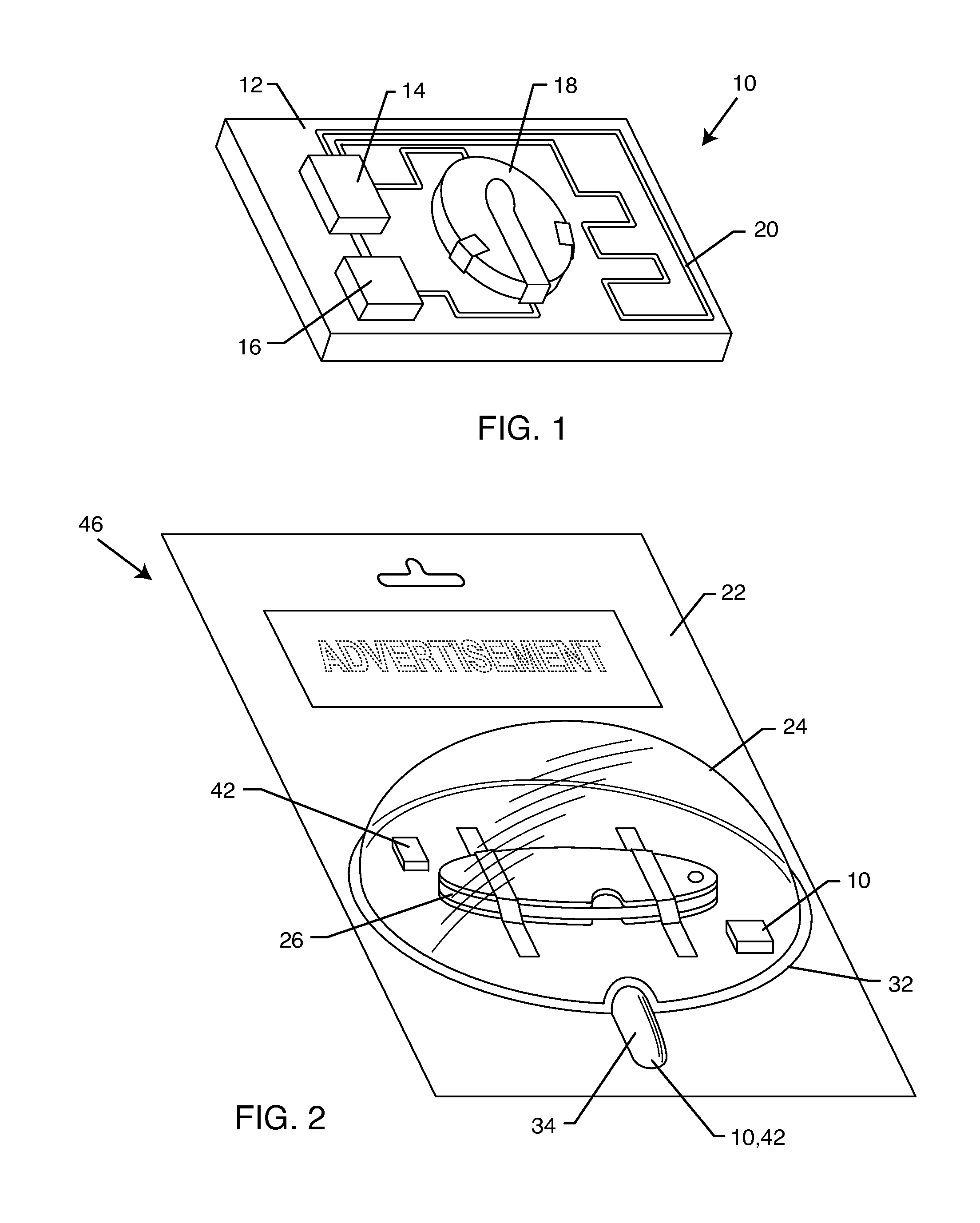
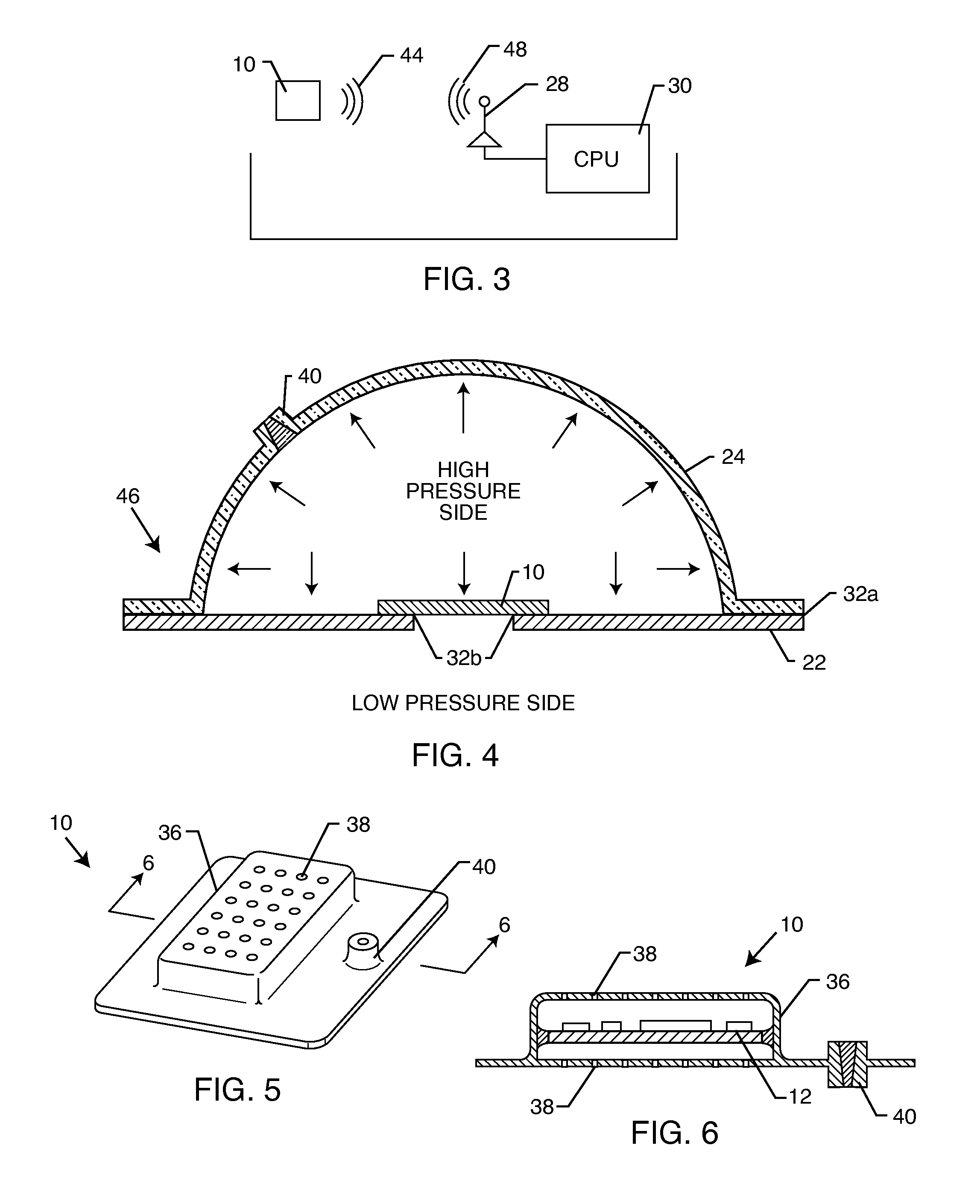
[0039]FIGS. 1-10 generally concern a theft-proof packaging system which includes a product package having a compartment configured to encapsulate a product, wherein the compartment is pneumatically pressurized above a surrounding environment. A pressure sensor assembly is located within the compartment. The pressure sensor assembly includes a pressure sensor, a power source electrically connected to the pressure sensor and a transmitter electrically connected to the power source. The transmitter is configured to send a signal. A receiving unit is located outside the compartment of the product package and disposed remote from the product package. The receiving unit includes a receiver configured to receive the signal from the transmitter and an alarm electrically coupled to the receiver. The pressure sensor assembly is configured to detect a change in pressure inside the compartment and then send the signal to the receiving unit activating the alarm.

[0040]The alarm may comprise a lig...


PUM


Abstract

A modular wall paneling system includes at least two plates. Each plate defines a longitudinal length, and each plate has a plurality of fixture apertures disposed through the plate along the longitudinal length. Each plate has a plurality of panel apertures disposed through plate along the longitudinal length. The plurality of fixture apertures are generally parallel to the plurality of fixture apertures. Included are a plurality of panels, each panel having a panel substrate and each panel having at least two hooks disposed on a backside of the panel substrate. Each of the at least two hooks are configured to removably lock into the panel apertures of the at least two plates.

Description

CROSS-REFERENCE TO RELATED APPLICATIONS[0001]This application is a continuation-in-part application that claims priority to application Ser. No. 14 / 214,817 filed on Mar. 15, 2014, which itself claimed priority to provisional application 61 / 786,597 filed on Mar. 15, 2013, the contents of which all applications are fully incorporated herein with this reference.FIELD OF THE INVENTION[0002]The present invention generally relates to a modular wall paneling system that allows quick and easy replacement of a variety of different types of panels.BACKGROUND OF THE INVENTION[0003]The present invention discloses two inventions, the first being directed to a pilf / theft resistant packaging system and the second being directed to a modular wall panel system.[0004]The first invention concerns pilf resistant packaging and systems thereof. Theft of various products from within a store is a huge problem. A thief will literally cut a product out of the clear plastic packaging and steal the product aft...

Claims


Application Information

Patent Timeline
Patent Type & Authority Applications(United States)
IPC IPC(8): E04F13/24E04B2/02E04B2/46E04B2/72
CPCE04F13/24E04B2/02E04B2002/0202E04B2/721E04B2/46B65D73/0014E04F13/083E04B2/7457G08B13/20H01H35/346B65D2203/10B65D2211/00E04B2002/7466E04B2002/7483E04B2002/7487G01M3/3272
Inventor MARTINO, MARC, G.
Owner MARTINO MARC G
Learn More