Pump Arrangement

a technology of pump arrangement and pump body, applied in the direction of positive displacement liquid engine, pump components, non-positive displacement fluid engine, etc., can solve the problems of assembling and disassembling, not inconsiderable level of outlay, and the overall efficiency of the pump arrangement is reduced, so as to achieve simple and inexpensive production and improve flow guidance.

Active Publication Date: 2016-03-24
KSB AG
View PDF26 Cites 10 Cited by
  • Summary
  • Abstract
  • Description
  • Claims
  • Application Information

AI Technical Summary

Benefits of technology

[0011]In a further refinement, it is proposed that the impeller channels have a channel base which is similar in form to a rampant three-center arch. This leads to an improvement in flow guidance.
[0012]In a further refinement of the invention, it is provided that the upper side of the vanes opposite the rear shroud, has a step close to the channel inlet edge. The step serves as an abutment shoulder and centering device for precise alignment of the auxiliary impeller fastened to the inner rotor.
[0013]For simple and inexpensive production, the impeller shaft and the inner rotor form a cover shroud, situated opposite the rear shroud, of the auxiliary impeller.

Problems solved by technology

However, said embodiment, with regard to its efficiency, constitutes an inefficient impeller or delivery variant, and lowers the overall efficiency of the pump arrangement.
Furthermore, a not inconsiderable level of outlay is required to produce the auxiliary impeller.
Furthermore, the impeller does not have a hub and is easy to assemble and disassemble.

Method used


Image

  • Pump Arrangement
  • Pump Arrangement
  • Pump Arrangement

Examples


Embodiment Construction

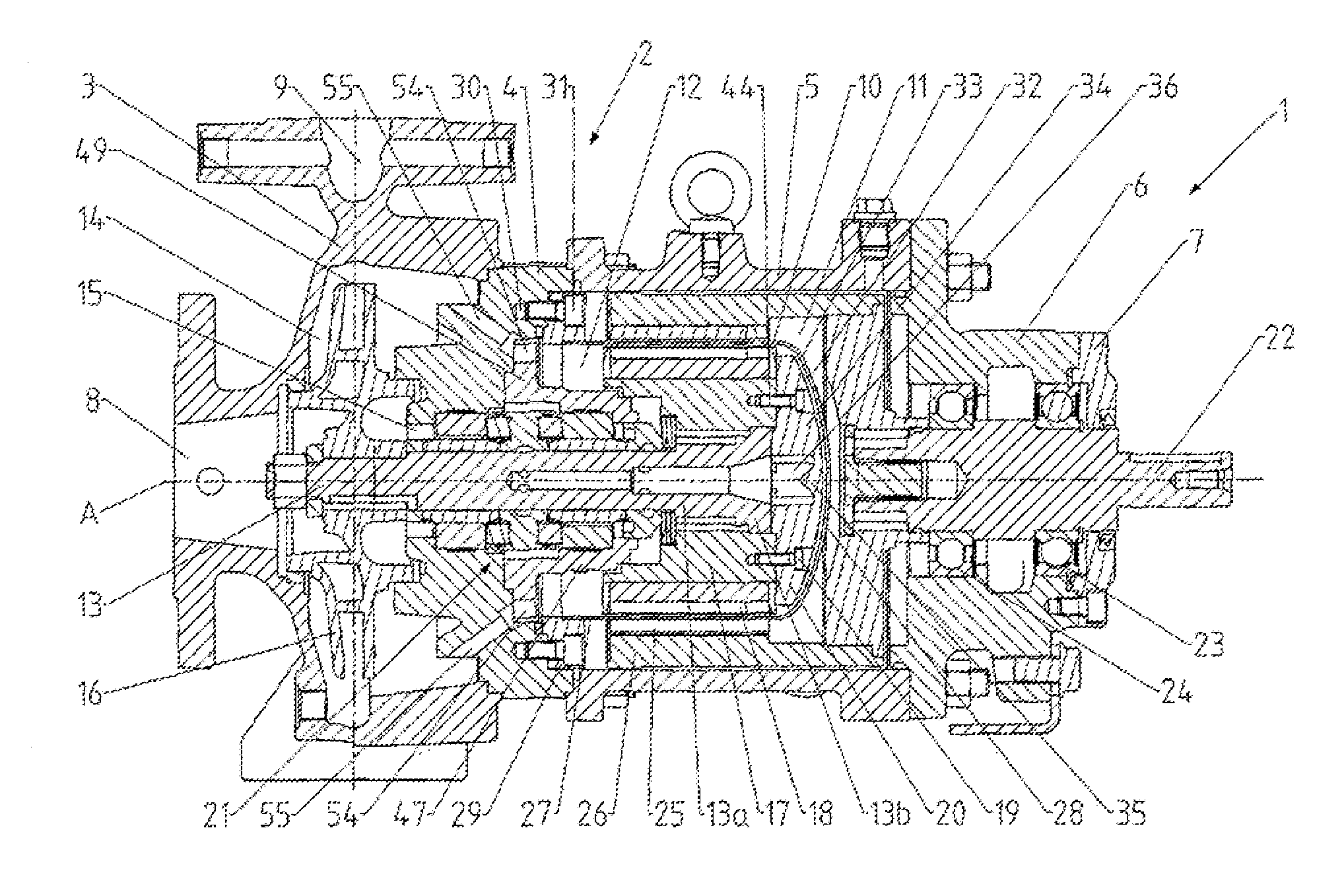
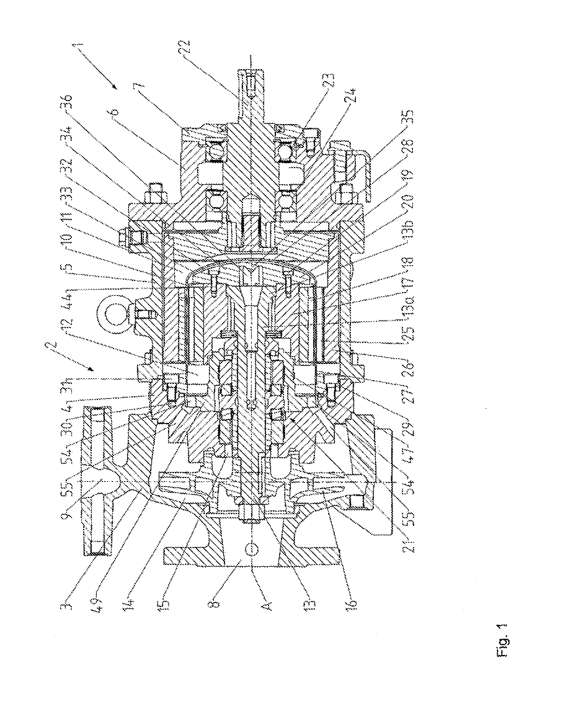
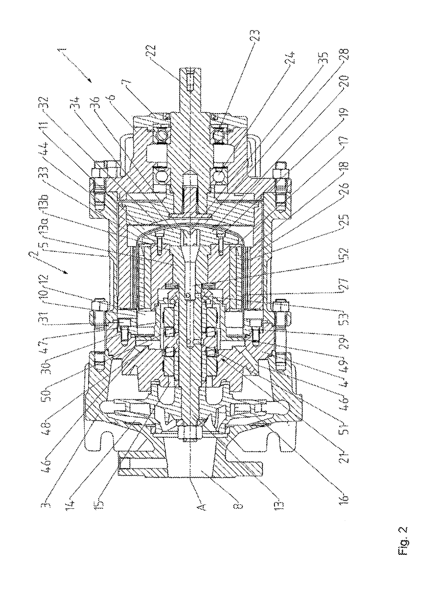
[0027]FIGS. 1 and 2 show a pump arrangement 1 in the form of a magnetic clutch pump arrangement. The pump arrangement 1 has a multi-part pump casing 2 of a centrifugal pump, which pump casing comprises a hydraulic casing 3 in the form of a spiral casing, a casing cover 4, a bearing carrier cage 5, a bearing carrier 6 and a bearing cover 7.

[0028]The hydraulic casing 3 has an inlet opening 8 for the intake of a delivery medium and has an outlet opening 9 for the discharge of the delivery medium. The casing cover 4 is arranged on that side of the hydraulic casing 3 which is situated opposite the inlet opening 8. The bearing carrier cage 5 is fastened to that side of the casing cover 4 which is opposite from the hydraulic casing 3. The bearing carrier 6 is mounted on that side of the bearing carrier cage 5 which is situated opposite the casing cover 4. The bearing cover 7 in turn is fastened to that side of the bearing carrier 6 which is opposite from the bearing carrier cage 5.

[0029]A ...


PUM


Abstract

A pump arrangement, in particular a magnetic clutch pump arrangement, is provided. The pump arrangement includes a pump housing containing an impeller shaft, a containment shell which seals an enclosed chamber within the inner chamber of the pump housing, an impeller mounted on one end of the impeller shaft, an inner rotor mounted on the other end of the impeller shaft, an outer rotor which is mounted on the drive shaft and co-operates with the inner rotor, and an auxiliary impeller mounted in the chamber adjacent to a domed base of the containment can. The auxiliary impeller is secured to the inner rotor and includes vanes and impeller channels for circulation of media.

Description

CROSS REFERENCE TO RELATED APPLICATIONS[0001]This application is a continuation of PCT International Application No. PCT / EP2014 / 058706, filed Apr. 29, 2014, which claims priority under 35 U.S.C. §119 from German Patent Application No. 10 2013 007 849.0, filed May 8, 2013, the entire disclosures of which are herein expressly incorporated by reference.BACKGROUND AND SUMMARY OF THE INVENTION[0002]The invention relates to a pump arrangement, in particular magnetic clutch pump arrangement. The pump arrangement has an interior space formed by a pump casing a containment can which hermetically seals off a chamber surrounded by said containment can with respect to the interior space formed by the pump casing, an impeller shaft which can be driven in rotation about an axis of rotation, an impeller which is arranged on one end of the impeller shaft, an inner rotor arranged on the other end of the impeller shaft, an auxiliary impeller arranged in the chamber, and an outer rotor which interacts...

Claims


Application Information

Patent Timeline
Patent Type & Authority Applications(United States)
IPC IPC(8): F04D13/06F04D29/043F04D29/08F04D29/18F04D29/22F04D29/42F04D29/44F04D29/52F04D29/54
CPCF04D13/0626F04D13/064F04D29/043F04D29/086F04D29/528F04D29/181F04D29/445F04D29/426F04D29/548F04D29/22F04D13/025F04D13/024F04D29/588F04D29/061F04D29/5873
Inventor DRECHSEL, PATRICKENGELBRECHT, JOERGGROESCHEL, JUERGENJAEGER, CHRISTOPHLAY, MARKUSWETZEL, WOLFRAM
Owner KSB AG
Why Eureka
Try Eureka