Sensor for detecting particles

a particle detection and sensor technology, applied in the field of particles detection sensors, can solve the problems of not fully utilizing the electrode surface, the accumulation of soot particles no longer a function of the exhaust gas velocity, and the insufficient charge of the electrode system with particles

Active Publication Date: 2018-08-02
ROBERT BOSCH GMBH
View PDF7 Cites 1 Cited by
  • Summary
  • Abstract
  • Description
  • Claims
  • Application Information

AI Technical Summary

Problems solved by technology

The disadvantage of this uniform, laminar flow-over is that although many soot particles skim past the electrode system, the electrode system is not necessarily fully charged with particles.
However, this occurs only in layers close to the electrode surface.
Hence, the available electrode surface is not fully utilized.
In addition, the accumulation of soot particles is no longer a function of the exhaust gas velocity.

Method used


Image

  • Sensor for detecting particles
  • Sensor for detecting particles
  • Sensor for detecting particles

Examples


Embodiment Construction

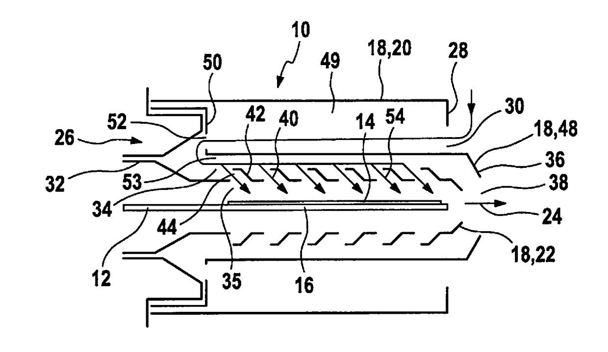
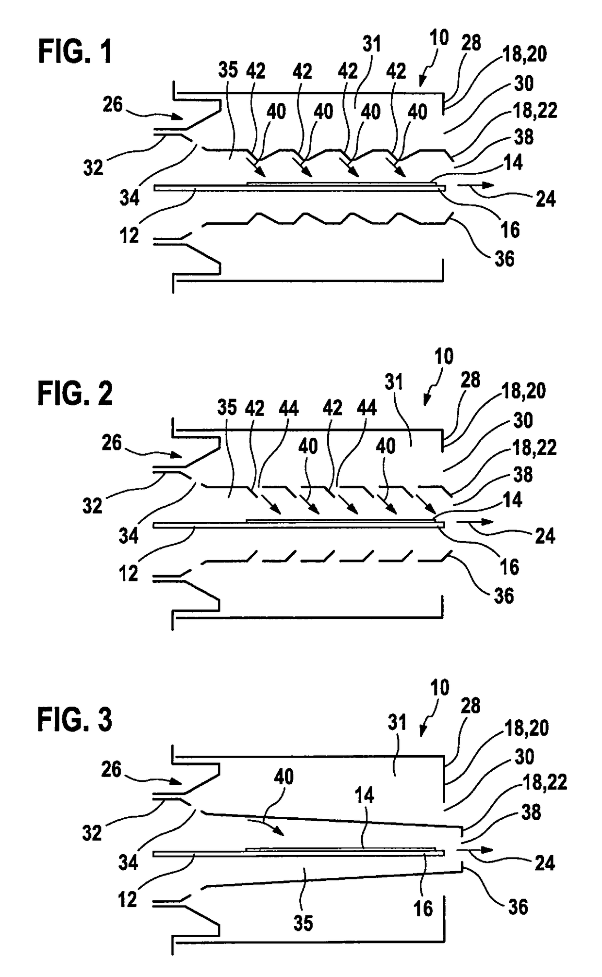
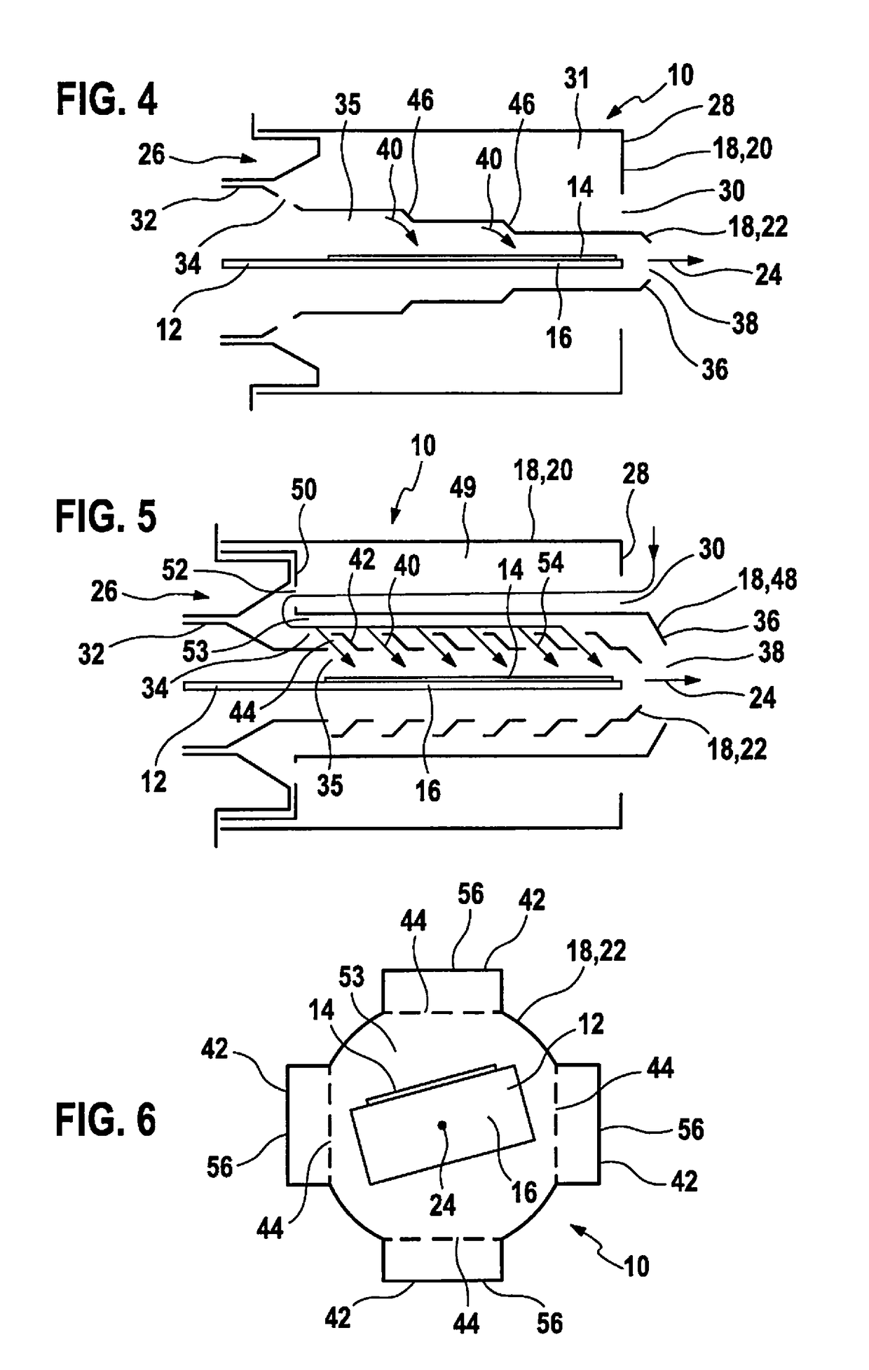
[0035]FIG. 1 shows a longitudinal sectional view of a sensor 10 for detecting particles, in particular, soot particles in a gas flow such as, for example, an exhaust gas flow of an internal combustion engine, which is suited for installation in an exhaust gas system of a motor vehicle. Sensor 10 is designed, for example, as a soot sensor and situated preferably downstream from a soot particle filter of a motor vehicle having a diesel combustion engine. Sensor 10 includes a sensor element 12 having at least two measuring electrodes 14, which are situated on a carrier substrate 16. Carrier substrate 16 may be manufactured from a ceramic material such as, for example, silicon oxide and / or aluminum oxide and / or zirconium oxide. The measuring electrodes 14 may be situated on carrier substrate 16, in particular, as interdigital electrodes.

[0036]Sensor 10 also includes a protective tube assembly 18 having at least one outer protective tube 20 and one inner protective tube 22. Sensor elemen...


PUM

PropertyMeasurementUnit
lengthsaaaaaaaaaa
lengthaaaaaaaaaa
shapeaaaaaaaaaa

Abstract

A sensor for detecting particles, in particular, soot particles, is described. The sensor includes a sensor element having at least two measuring electrodes, which are situated on a carrier substrate, and a protective tube assembly having at least one outer protective tube and one inner protective tube. The sensor element is situated in the inner protective tube in a longitudinal extension direction. The outer protective tube and the inner protective tube are designed to permit the particles to access the sensor element in a direction deviating from the longitudinal extension direction.

Description

BACKGROUND INFORMATION[0001]Numerous conventional methods and devices are available for detecting particles such as, for example, soot or dust particles.[0002]The present invention is described below, without limitation to additional specific embodiments and specific applications, in particular, with reference to sensors for detecting particles, in particular, soot particles in an exhaust gas flow of an internal combustion engine.[0003]Conventionally, a concentration of particles is measured, for example, soot particles or dust particles in an exhaust gas, with the aid of two electrodes which are situated on a ceramic. This may take place, for example, by measuring the electrical resistance of the ceramic material separating the two electrodes. More precisely, the electrical current is measured, which flows between the electrodes when a voltage is applied to them. The soot particles accumulate between the electrodes due to electrostatic forces and in time form electrically conductiv...

Claims


Application Information

Patent Timeline
Patent Type & Authority Applications(United States)
IPC IPC(8): G01N15/06F01N13/00
CPCG01N15/0656G01N15/0606F01N13/008G01N2015/0046F01N2560/05G01N15/06G01N27/403
Inventor TIEFENBACH, ANDYHOLZKNECHT, CHRISTOPHERBAARS, ENNOFREIKAMP, FRANKBESSEN, MICHAEL
Owner ROBERT BOSCH GMBH
Why Eureka
Try Eureka