Pump Arrangement

a technology of pump arrangement and rotor, which is applied in the direction of machines/engines, liquid fuel engines, positive displacement liquid engines, etc., can solve the problems of large torque range and unavoidable adaptability of rotors, and achieve the effect of improving the flow guidance of the medium, facilitating and thus reducing production costs

Active Publication Date: 2016-04-21
KSB AG
View PDF9 Cites 2 Cited by
  • Summary
  • Abstract
  • Description
  • Claims
  • Application Information

AI Technical Summary

Benefits of technology

[0010]In a further refinement, the abutment surface has a region which is recessed in an axial direction and into which a centering ring formed on the mounting flange engages. It is firstly possible for a seal ring to be arranged in the recessed region, and secondly, the adapter element can be aligned exactly and fastened in fluid-tight fashion to the casing cover.
[0011]By virtue of the fact that, on the side situated opposite the mounting flange, the adapter element has multiple threaded holes for the fastening of the containment can, it is possible, within one magnetic clutch size, to use or interchange different containment cans of different pressure stages or strengths and / or different materials.
[0012]According to the invention, on the side situated opposite the mounting flange, a ring is provided which extends further in the axial direction into the interior space, which ring forms a run-on safeguard and prevents contact between the outer rotor and the containment can.
[0013]To improve the flow guidance of the medium, and for easier and thus cheaper production by casting, the outer contour of the adapter element has a substantially conical profile.
[0014]Here, the adapter element preferably narrows, substantially proceeding from the mounting flange toward the ring.
[0015]In a further refinement, it is provided that that end of the outer rotor which points in the direction of the casing cover has a radially encircling projection. In this way, the radial spacing of the outer rotor to the ring for normal operation can be produced in an exact manner.

Problems solved by technology

Above a certain structural size, an adaptation of the rotor size is unavoidable.
The documents cited above however do not take into consideration that, owing to different rotational speeds, delivery heights, delivery volumes and densities of the medium to be delivered, a large range of torques is required for a given hydraulic size.

Method used


Image

  • Pump Arrangement
  • Pump Arrangement
  • Pump Arrangement

Examples


Embodiment Construction

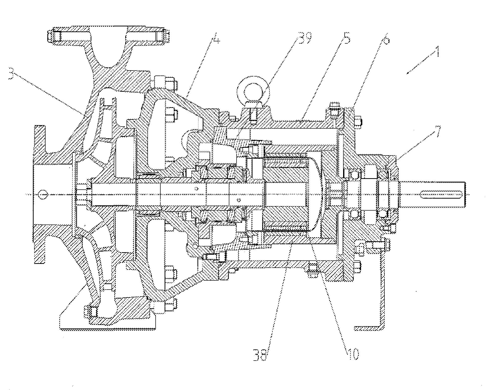
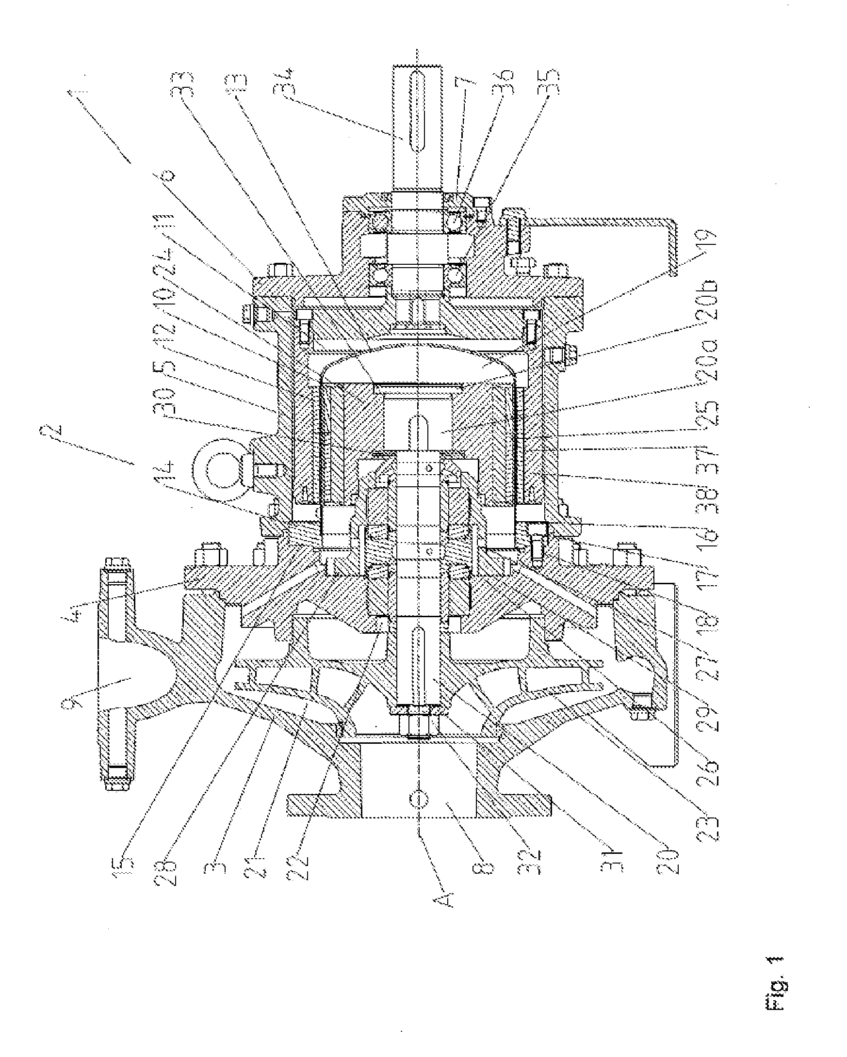
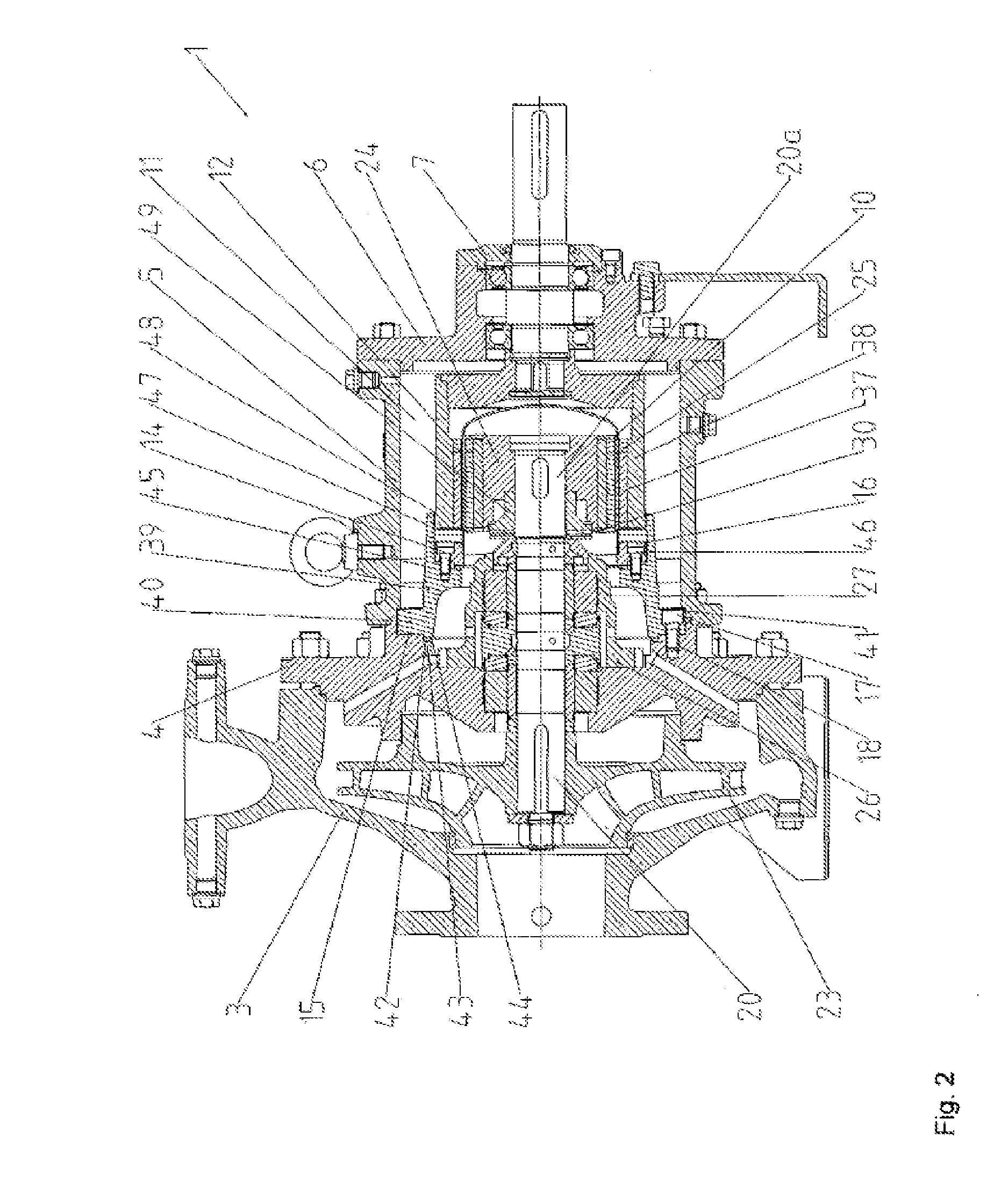
[0026]FIG. 1 shows a pump arrangement 1 in the form of a magnetic clutch pump arrangement. The pump arrangement 1 has a multi-part pump casing 2 of a centrifugal pump, which pump casing comprises a hydraulics casing 3 in the form of a spiral casing, a casing cover 4, a bearing carrier cage 5, a bearing carrier 6 and a bearing cover 7.

[0027]The hydraulics casing 3 has an inlet opening 8 for the intake of a delivery medium and has an outlet opening 9 for the discharge of the delivery medium. The casing cover 4 is arranged on that side of the hydraulics casing 3 which is situated opposite the inlet opening 8. The bearing carrier cage 5 is fastened to that side of the casing cover 4 which is averted from the hydraulics casing 3. The bearing carrier 6 is mounted on that side of the bearing carrier cage 5 which is situated opposite the casing cover 4. The bearing cover 7 in turn is fastened to that side of the bearing carrier 6 which is averted from the bearing carrier cage 5.

[0028]A cont...


PUM


Abstract

A pump arrangement, in particular a magnetic coupling pump arrangement, includes a pump housing having an interior, a split case which hermetically seals a chamber surrounded by the split case from the interior formed by the pump housing, an impeller shaft with an impeller thereon which can be driven in a rotatable manner about a rotational axis, an inner rotor arranged at an end of the impeller shaft opposite the impeller end, an outer rotor which interacts with the inner rotor, and an adapter element which connects the split case to the pump housing or to a component paired with the pump housing, in particular a housing cover. The adapter element includes a mounting flange which rests against a support surface of the pump housing, in particular of the housing cover (4), on a face adjacent to the interior.

Description

CROSS REFERENCE TO RELATED APPLICATIONS[0001]This application is a continuation of PCT International Application No. PCT / EP2014 / 060197, filed May 19, 2014, which claims priority under 35 U.S.C. §119 from German Patent Application No. 10 2013 008 795.3, filed May 24, 2013, the entire disclosures of which are herein expressly incorporated by reference.BACKGROUND AND SUMMARY OF THE INVENTION[0002]The invention relates to a pump arrangement, in particular a magnetic clutch pump arrangement, having an interior space formed by a pump casing of the pump arrangement, having a containment can which hermetically seals off a chamber surrounded by said containment can with respect to the interior space formed by the pump casing, having an impeller shaft which can be driven in rotation about an axis of rotation, having an impeller which is arranged on one end of the impeller shaft, having an inner rotor arranged on the other end of the impeller shaft, and having an outer rotor which interacts wi...

Claims


Application Information

Patent Timeline
Patent Type & Authority Applications(United States)
IPC IPC(8): F04D25/06F04D17/10
CPCF04D17/10F04D25/06F04D13/025F04D13/024F04D29/628F04D13/026F04D13/02
Inventor DRECHSEL, PATRICKLAY, MARKUS
Owner KSB AG
Why Eureka
Try Eureka