Power transmission shaft and propeller shaft for vehicle

a technology of power transmission shaft and propeller shaft, which is applied in the direction of sealing, couplings, transportation and packaging, etc., can solve the problems of deteriorating shock absorption performance, affecting the smooth movement of cylindrical members relative to shaft members, and affecting the stability of the shaft, so as to achieve the effect of suppressing the lowering of shock absorption performan

Active Publication Date: 2016-03-24
HITACHI ASTEMO LTD
View PDF1 Cites 9 Cited by
  • Summary
  • Abstract
  • Description
  • Claims
  • Application Information

AI Technical Summary

Benefits of technology

[0011]According to the present invention, it is possible to prevent the annular seal member from being caught in the splines at a time of the movement of

Problems solved by technology

As a result, a sliding (movement) resistance between the both splines becomes large, and a smooth movement in a retracting directi

Method used


Image

  • Power transmission shaft and propeller shaft for vehicle
  • Power transmission shaft and propeller shaft for vehicle
  • Power transmission shaft and propeller shaft for vehicle

Examples


second embodiment

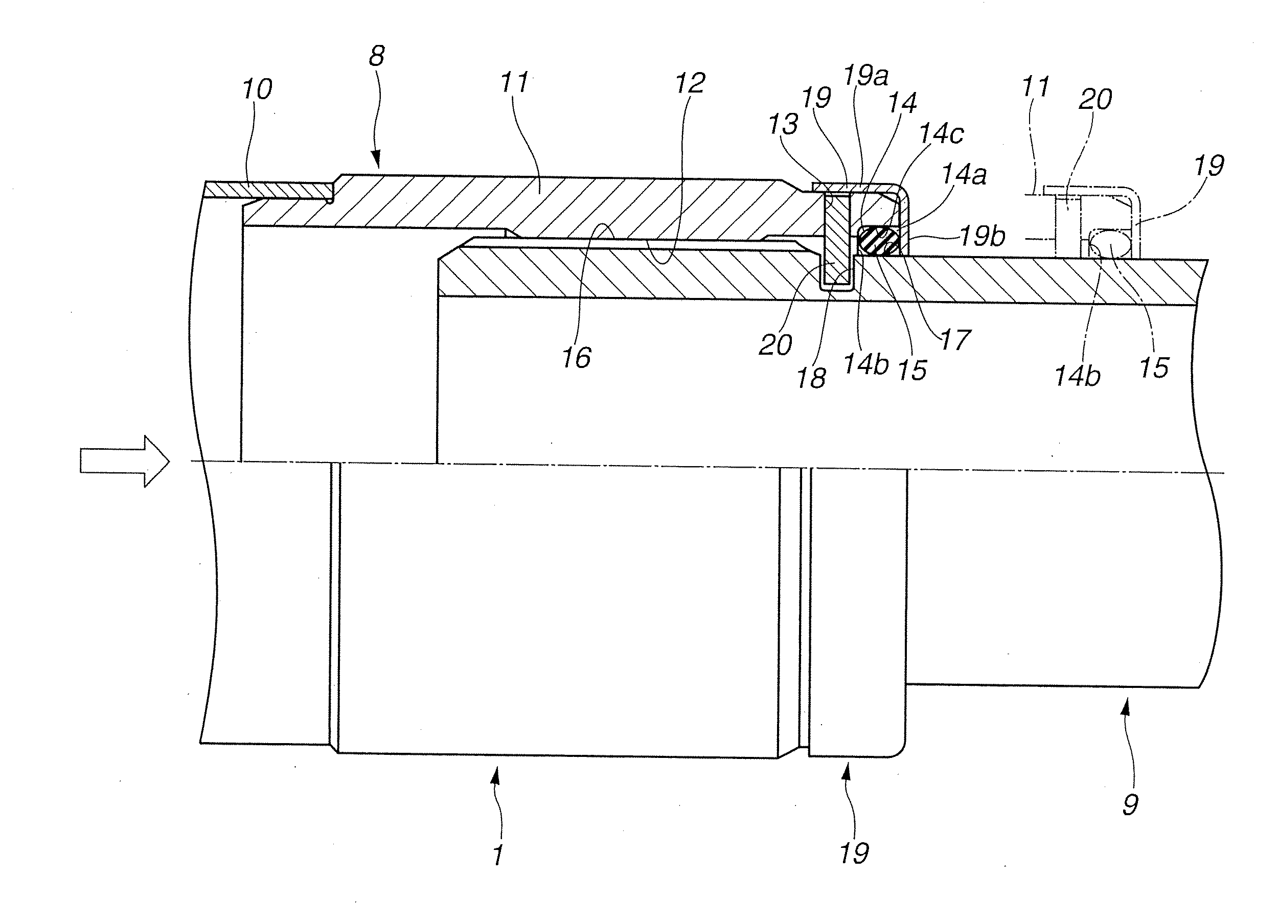
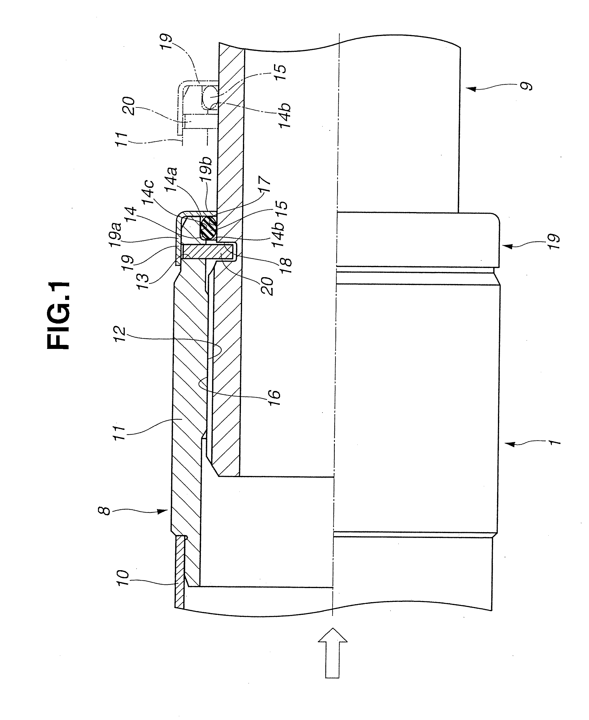
[0042]FIG. 3 shows a second embodiment of the present invention. A basic structure of the second embodiment is the same as the first embodiment. However, as a different structure, a non-seal surface 21 that is a small diameter portion having a smaller diameter than an outer diameter of the outer peripheral seal surface 17 is formed on the outer peripheral surface of the rear side shaft 9.

[0043]That is, the non-seal surface 21 is formed into a cylindrical shape having the smaller diameter than the outer diameter of the outer peripheral seal surface 17, and continues from one end edge position in the axial direction of the outer peripheral surface 17 to an almost all area “a” of the rear side shaft 9.

[0044]Therefore, as described above, when the excessive input-load is exerted on the front side shaft 8 of the first shaft 1 from an axial direction left side shown by an arrow in FIG. 3, for example, upon the collision of the vehicle, the large moving force to the direction of the rear s...

third embodiment

[0052]FIG. 5 shows a third embodiment of the present invention. A basic structure of the third embodiment is the same as the second embodiment. However, each of the engaging holes, the retaining pin and the retainer are not provided. Further, as the seal member, an oil seal 22 is used instead of the seal ring (o-shaped ring).

[0053]The oil seal 22 has a typical structure having a substantially bracket-shape in a cross section. The oil seal 22 has a circular base portion 22a which is press-fixed to the bottom surface 14c of the annular seal groove 14, a support portion 22b which is integrally formed with the base portion 22a and contacts the inside wall surface 14b and a seal portion 22c which is integrally formed with an inner peripheral side of the support portion 22b and contacts the outer peripheral seal surface 17 of the rear side shaft 9. The seal portion 22c is set so as to elastically contact the outer peripheral seal surface 17 all the time by a spring force of a backup sprin...

fourth embodiment

[0056]FIG. 6 shows a fourth embodiment. A basic structure of the fourth embodiment is the same as the second embodiment. However, in the fourth embodiment, a retaining pin 23 is provided at a front end portion 11a of the second tube 11 and a front end portion 9a of the rear side shaft 9.

[0057]That is, the retaining pin 23 is formed into a hollow cylindrical shape and a length of the retaining pin 23 is slightly smaller than an outer diameter of the front end portion 11a of the second tube 11.

[0058]The front end portion 11a of the second tube 11 has a large diameter and is formed to be thick. A first engaging hole 24 penetrates the front end portion 11a along a radially inward direction of the front end portion 11a. An inner diameter of the first engaging hole 24 is formed to be slightly larger than an outer diameter of the retaining pin 23 so that the retaining pin 23 is slightly press-fixed to the first engaging hole 24.

[0059]On the other hand, the inside of the rear side shaft 9 i...


PUM


Abstract

A power transmission shaft has a shaft member having, on an outer peripheral surface thereof, a male spline; a cylindrical member having, on an inner peripheral surface thereof, a female spline; and a seal member provided in a pressed state between an outer peripheral seal surface formed on the outer peripheral surface of the shaft member and an inner peripheral seal surface formed on the inner peripheral surface of the cylindrical member. The cylindrical member is spline-engaged with the shaft member by one end side of the shaft member being inserted into the cylindrical member from an other end side of the cylindrical member. Axial direction shock is absorbed by sliding of the splines. The outer peripheral seal surface is positioned at the other end side with respect to the male spline, and the inner peripheral seal surface is positioned at the other side with respect to the female spline.

Description

BACKGROUND OF THE INVENTION[0001]The present invention relates to an improvement of a power transmission shaft and a propeller shaft that transmit power from a transmission to a driving wheel of a vehicle.[0002]In recent years, there have been proposed and developed various power transmission shafts (propeller shafts). For example, Japanese Patent Application Publication No. 09-123774 (hereinafter is referred to as “JPH09-123774”) discloses in (FIG. 3) a power transmission shaft (a propeller shaft) mounted on a vehicle. The power transmission shaft (the propeller shaft) disclosed in JPH09-123774 has a cylindrical member whose axial direction front end portion is connected to a transmission side of the vehicle and a shaft member whose axial direction rear end portion is connected to a differential carrier side and which is connected to the cylindrical member from an axial direction.[0003]The cylindrical member is provided, on an inner peripheral surface of a rear end portion thereof,...

Claims


Application Information

Patent Timeline
IPC IPC(8): F16D1/10
CPCF16D2001/103F16D1/10B60K17/22F16C3/023F16D1/108F16D2300/08F16D3/06F16D3/84Y10T403/7026Y10S277/912
Inventor AKITA, YASUSHIKOMAI, HIROMICHIKUBO, MASASHI
Owner HITACHI ASTEMO LTD
Why Eureka
Try Eureka