Levelling spacer device for laying slab products for cladding surfaces

a technology of cladding surface and leveling spacer, which is applied in the direction of measuring devices, instruments, constructions, etc., can solve the problems of relative cost repercussions and drawbacks of being less handy to us

Active Publication Date: 2016-03-31
RAIMONDI
View PDF4 Cites 26 Cited by
  • Summary
  • Abstract
  • Description
  • Claims
  • Application Information

AI Technical Summary

Problems solved by technology

These levelling spacer devices, while on the one hand enabling reduction of the spatial volume thereof, also enable a more rational and efficient storage and transport thereof, with consequent beneficial repercussions on the relative costs; however they exhibit the drawback of being less handy to use for the personnel doing the laying, as once the separator element is positioned in the working position it does not remain in the desired position (squared with the base) but is free to return, even only by a limited angle, towards the storage position, for example by effect of a certain intrinsic elasticity of the material of which the levelling spacer device itself is made.
Further, the inclined or slightly inclined arrangement of the separator element does not enable the exact positioning of the tiles in the area of the device itself, defining therefore spaces between the tiles which are not perfectly regular and this is a problem for the positioning of the tiles which flank the tiles already laid.

Method used


Image

  • Levelling spacer device for laying slab products for cladding surfaces
  • Levelling spacer device for laying slab products for cladding surfaces
  • Levelling spacer device for laying slab products for cladding surfaces

Examples


first embodiment

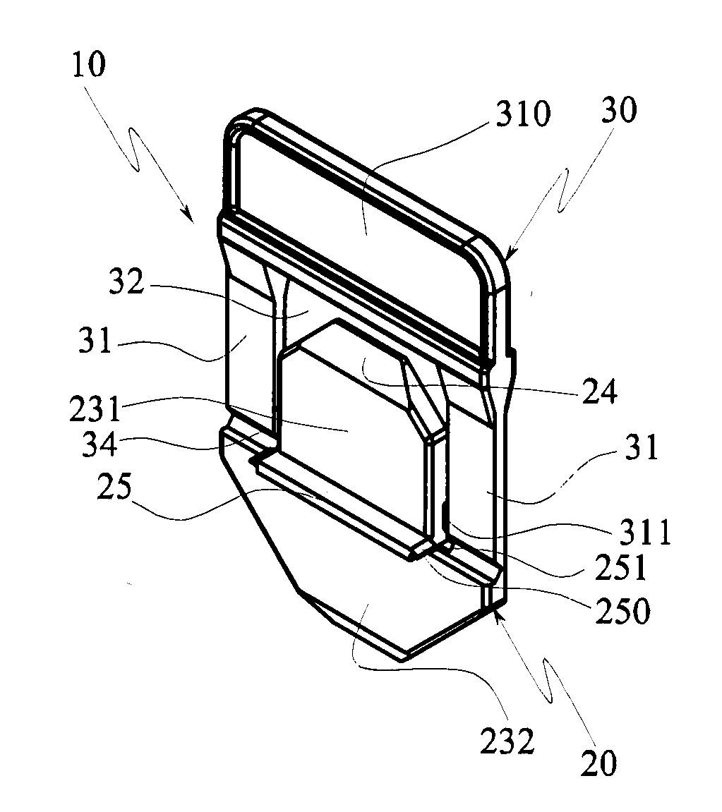
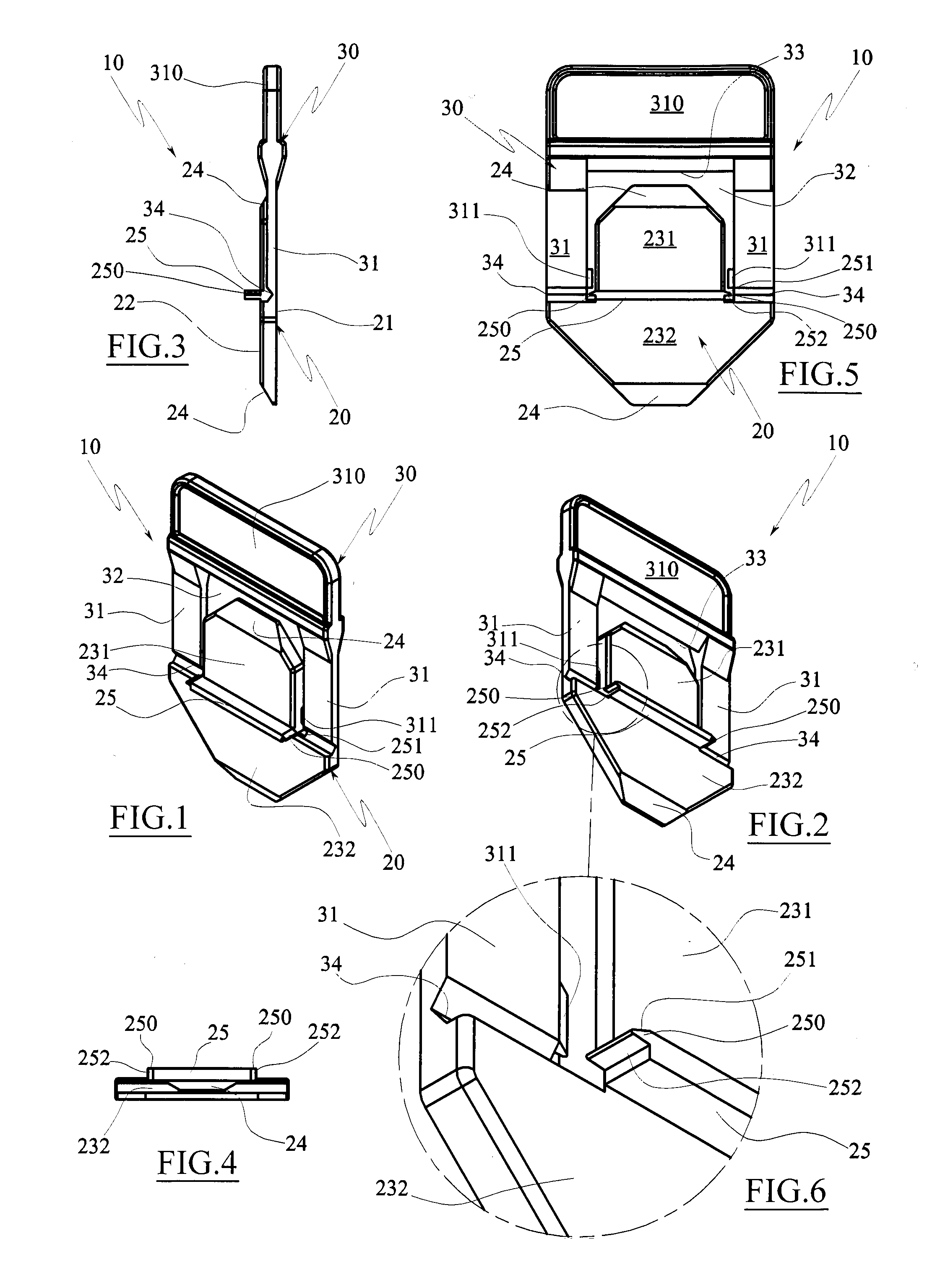
[0038]FIG. 1 is a first axonometric view of a levelling spacer device, according to the invention, in the storage position.

[0039]FIG. 2 is a second axonometric view of the levelling spacer device of FIG. 1.

[0040]FIG. 3 is a lateral view of FIG. 1.

[0041]FIG. 4 is a front view of FIG. 1.

[0042]FIG. 5 is a view from above of FIG. 1.

[0043]FIG. 6 is a larger-scale detail of FIG. 2.

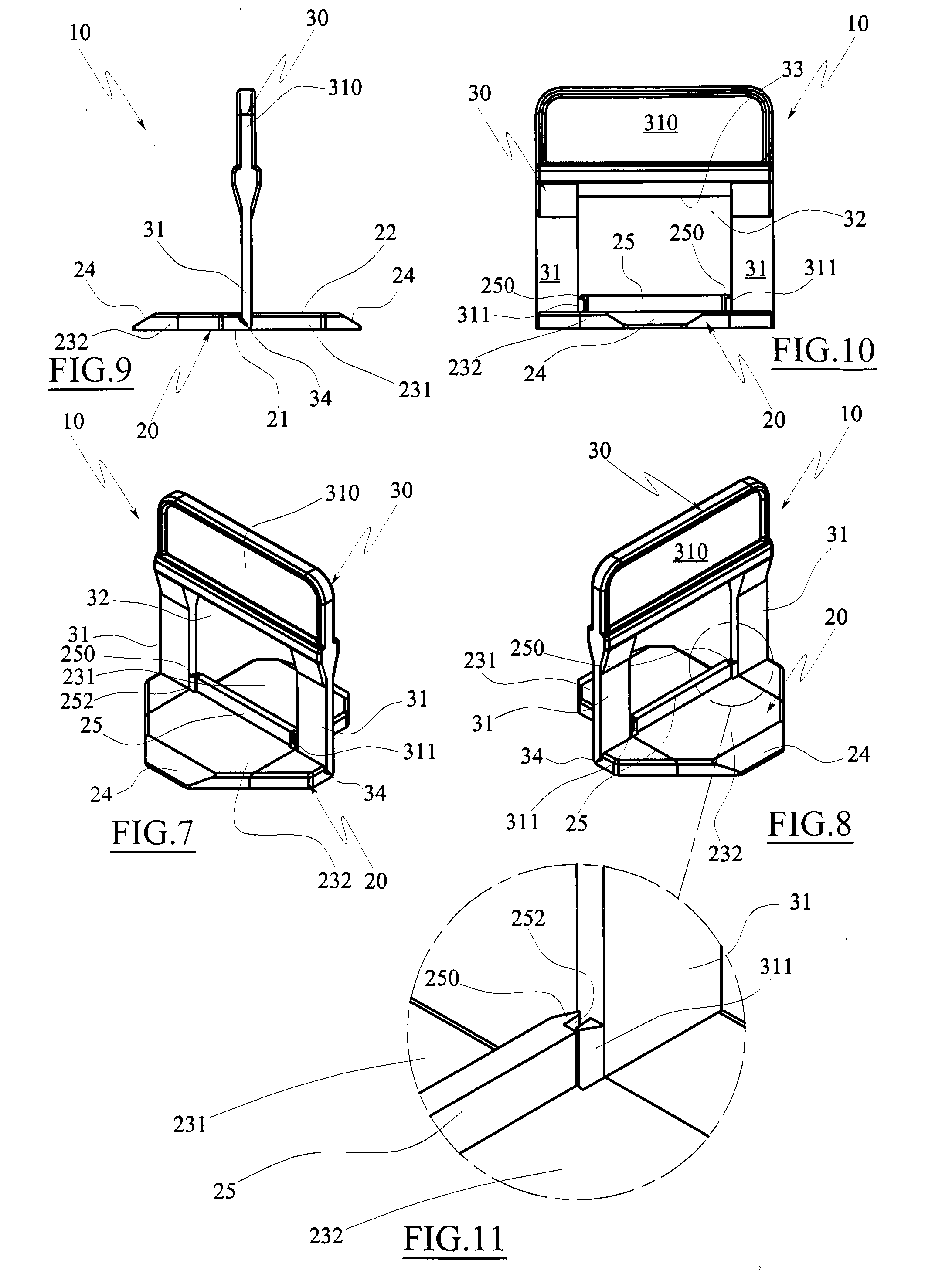
[0044]FIG. 7 is a first axonometric view of the levelling spacer device, according to the first embodiment of the invention, in an operator work position.

[0045]FIG. 8 is a second axonometric view of the levelling spacer device of FIG. 7.

[0046]FIG. 9 is a lateral view of FIG. 7.

[0047]FIG. 10 is a front view of FIG. 7.

[0048]FIG. 11 is a larger-scale detail of FIG. 8.

second embodiment

[0049]FIG. 12 is a first axonometric view of a levelling spacer device according to the invention, in the storage position.

[0050]FIG. 13 is a second axonometric view of the levelling spacer device of FIG. 12.

[0051]FIG. 14 is a lateral view of FIG. 12.

[0052]FIG. 15 is a view from above of FIG. 12.

[0053]FIG. 16 is an axonometric view of the levelling space device according to the second embodiment of the invention, in the operative work position.

[0054]FIG. 17 is a lateral view of FIG. 16.

[0055]FIG. 18 is a view from above of FIG. 16.

[0056]FIG. 19 is a lateral view of the device of FIG. 16 with a wedge inserted for levelling a slab product.

[0057]FIGS. 20 and 21 are views from above of the device of FIG. 16 with a possible arrangement of slab products and, respectively, before or after the inserting of the wedge for the levelling of the slabs.

third embodiment

[0058]FIG. 22 is an axonometric view of a levelling spacer device, according to the invention, in the storage position.

[0059]FIG. 23 is a lateral view of FIG. 22.

[0060]FIG. 24 is a view from above of FIG. 22.

[0061]FIG. 25 is a lateral view of the levelling spacer device according to the third embodiment of the invention, in an operative work position.

[0062]FIG. 26 is an axonometric view of FIG. 25.


PUM


Abstract

A levelling spacer device (10) for laying slab products (P) for cladding surfaces, which device (10) comprises a base (20), positionable on a backside of a laying surface of at least two slab products (P) that are adjacent and flanked with respect to a flanking direction (A), at least a separator element (30) emerging from the base (20), able to contact the facing flanks of the two slab products (P), and mobile between a storage position in which it lies substantially parallel to the base (20) and a work position in which it emerges substantially perpendicular to the base (20); the peculiarity of the device consisting in the fact of comprising blocking means (250, 311) of the separator element (30) in the work position.

Description

TECHNICAL FIELD[0001]The present invention relates to a levelling spacer device for laying slab products, natural slab products and the like, for cladding surfaces, such as treadable surfaces, floors, wall coverings or ceilings and the like.PRIOR ART[0002]In the sector of laying tiles for cladding surfaces, such as floors, walls and the like, the use of spacer devices is known, which not only space the tiles but enable planar arrangement thereof. These devices are commonly known as levelling spacer devices.[0003]The levelling spacer devices of known type generally comprise a base, positionable below the laying surface of at least two adjacent tiles, from which at least a separator element emerges, able to contact, by means of the lateral flanks thereof, the facing flanks of the two tiles to be laid side-by-side on the laying surface.[0004]The levelling spacer device is also provided with presser means able to press the in-view surface of the products toward the base in such a way as...

Claims


Application Information

Patent Timeline
Patent Type & Authority Applications(United States)
IPC IPC(8): E04F21/00E04F21/18
CPCE04F21/18E04F21/0092
Inventor SIGHINOLFI, RICCARDO
Owner RAIMONDI
Why Eureka
Try Eureka