
LED tube light

a technology of led tubes and led tubes, applied in the field of led tubes, can solve the problems of reducing the overall lighting or luminous efficiency of led tubes, reducing the luminous efficiency, and causing accidental electrical shock to users, so as to improve light transmittance, prevent accidental electrical shock, and maximize illumination efficiency

Active Publication Date: 2016-03-31
JIAXING SUPER LIGHTING ELECTRIC APPLIANCE
View PDF17 Cites 51 Cited by
  • Summary
  • Abstract
  • Description
  • Claims
  • Application Information

AI Technical Summary

Benefits of technology

The present invention provides an LED tube light with an optical adhesive coating that is between 1.1 mm to 1.3 mm thick and clear or transparent in color. The refractive index of the optical adhesive is optimized to produce optimal illumination efficiency. The optical adhesive is transparent, improves light transmittance, and provides insulating function. The glass light tube containing the adhesive film layer can prevent accidental electrical shock and achieve more evenly distributed LED light tube illumination, higher light transmittance. The adhesive film layer is made of calcium carbonate, thickening agent, ceramic activated carbon, and deionized water, which are mixed and combined together to be evenly coated on the side wall surface of the glass tube, with average thickness of 20-30 microns. Evaporation of the deionized water leaves behind the calcium carbonate, thickening agent, and ceramic activated carbon.

Problems solved by technology

The technical problem addressed in this patent is the quality issues and production bottlenecks of conventional LED tube lights caused by the conventional assembly and fabrication methods, including the use of plastic end caps that can easily break, the need for adhesive bonding that is time-consuming and requires manual labor, the potential for electrical shock incidents due to the use of fragile glass tubes, and the buildup and light blockage of excess adhesive residues.

Method used


Image

  • LED tube light
  • LED tube light
  • LED tube light

Examples


second embodiment

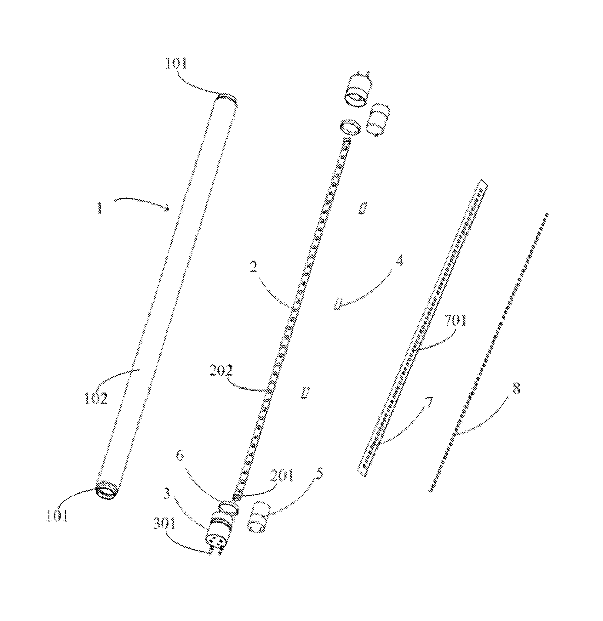
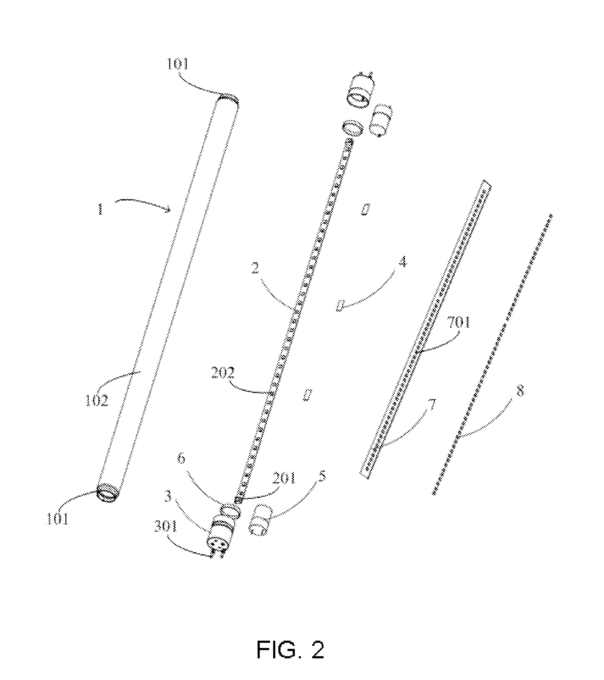
[0053]The thermal conductive ring can be made of various heat conducting materials, the thermal conductive ring 303 of the present embodiment is a metal sheet, such as aluminum alloy. The thermal conductive ring 303 being tubular or ring shaped, is being sleeved over the second tubular part 302b. The insulating tubular part 302 may be made of insulating material, but would have low thermal conductivity so as to prevent the heat conduction to reach the power supply components located inside the end cap 3, which then negatively affect performance of the power supply components. In this embodiment, the insulating tubular part 302 is a plastic tube. In other embodiments, the thermal conductive ring 303 may also be formed by a plurality of metal plates arranged along a plurality of second tubular part 302b in either circumferentially-spaced or not circumferentially-spaced arrangement. In other embodiments, the end cap may take on or have other structures. Referring to FIGS. 8-9, the end ...

first embodiment

[0062]To improve the illumination efficiency of the LED tube light, the light tube 1 has been modified or customized according to present invention by having a diffusion film layer 13 coated and bonded to the inner wall thereof as shown in FIG. 12. The diffusion film layer 13 allows for improved illumination distribution uniformity of the light outputted by the LED light sources 202. The diffusion film layer 13 can be coated onto different locations, such as onto the inner wall of the light tube 1 or onto the diffusion coating layer (not shown) at the surface of each LED light source 202, or coated onto a separate membrane cover covering the LED light source 202. The diffusion film layer 13 in the illustrated embodiment is a diffusion film that is not in contact with the LED light source 202. The diffusion layer 13 can be an optical diffusion film or sheet, usually made of polystyrene (PS), polymethyl methacrylate (PMMA), polyethylene terephthalate (PET), and / or polycarbonate (PET),...


PUM

PropertyMeasurementUnit
Fractionaaaaaaaaaa
Thicknessaaaaaaaaaa
Thicknessaaaaaaaaaa

Abstract

An LED tube light having a substantially uniform exterior diameter from end to end is disclosed. It has a glass light tube with narrowly curved end regions at ends for engaging with end caps, in which outer diameter of each end cap is equal to outer diameter of light tube. LED tube light also include a thermal conductive ring. The narrowly curved end region is formed by glass tempering. End caps are joined to the light tube by sleeving over the rear end regions with a hot melt adhesive disposed between the rear end region, the transition region, the insulating tubular part and the thermal conductive ring. An outer diameter of thermal conductive ring is the same as the outer diameter of the main region of the light tube. The transition region is curved, and an outer diameter of rear end region is less than that of the main region.

Description


Claims


Application Information

Patent Timeline
Owner JIAXING SUPER LIGHTING ELECTRIC APPLIANCE
Features
  • Generate Ideas
  • Intellectual Property
  • Life Sciences
  • Materials
  • Tech Scout
  • Unparalleled Data Quality
  • Higher Quality Content
  • 60% Fewer Hallucinations
Learn More