
System and method for stabilizing a voice coil

Active Publication Date: 2016-03-31
SHENZHEN MINDRAY BIO MEDICAL ELECTRONICS CO LTD
View PDF19 Cites 2 Cited by
  • Summary
  • Abstract
  • Description
  • Claims
  • Application Information

AI Technical Summary

Benefits of technology

This patent describes a device and method that allows for adjusting and optimizing the damping of a voice coil used to provide a motive force for a patient. By adjusting damping, the device can effectively control parameters like PEEP-pressure or the inspiratory flow and pressure, leading to improved ventilation and reduced work of breathing for patients. The device is easy to implant without adding any further sensors and can be used with existing sensors. Additionally, the patent describes a negative gain to cancel out or lessen the effects of the inherent motional electromotive force in the voice coil. Damping is defined as a force that has a stabilizing effect and is directed in the opposite direction of movement.

Problems solved by technology

Other characteristics with the current technology are that membranes inside the valve may create spring forces and the voice coil is not ideal.
A significant drawback with this kind of valve is that it is not stable.
A valve that is not stable will vibrate and consequently cause oscillations in the flow and pressure.
Using normal pressure or flow feedback to stabilize the valve is complicated since the oscillations can be fast and it is difficult to make any conclusion of the movement of the valve just by measuring the pressure or flow.
Using friction is another way to prevent oscillations, but it is not desired since it may make the PEEP pressure control inferior.
A major drawback with conventional viscous damping is that the viscous damping coefficient is constant while the actual needed damping varies a lot depending on the pressure and also on the flow.
The drawback with having a too high damping coefficient is that the valve responds slowly to control signals as well as to changes in the flow rate which can result in that the valve will not be able to control a constant PEEP pressure.
Using a low constant viscous damping coefficient would mean that the system would be unstable for high pressures, while using a high damping coefficient would mean that the valve would respond too slowly for low pressures.
Further possibilities are positional or velocity feedback by use of a positional or velocity sensor, with the drawbacks of increased cost and complexibility.
When controlling, for example, the pressure and the flow during inspiration using a voice coil motor the system also demonstrates issues with stabilization.

Method used


Image

  • System and method for stabilizing a voice coil
  • System and method for stabilizing a voice coil
  • System and method for stabilizing a voice coil

Examples


Embodiment Construction

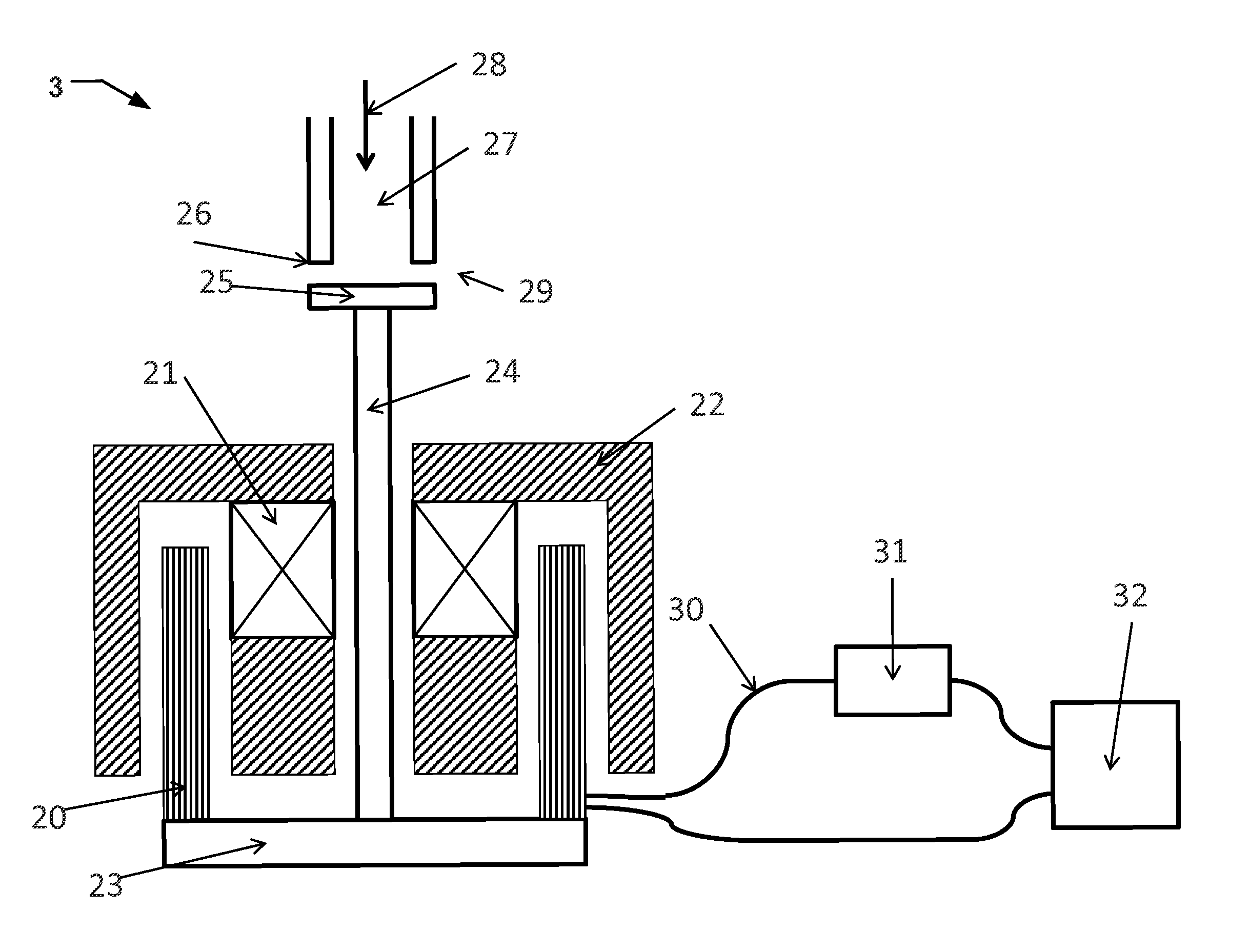
[0035]Specific examples of the disclosure will now be described with reference to the accompanying drawings. This disclosure may, however, be embodied in many different forms and should not be construed as limited to the examples set forth herein; rather, these examples are provided so that this disclosure will be thorough and complete, and will fully convey the scope of the disclosure to those skilled in the art.

[0036]While several examples of the present disclosure have been described and illustrated herein, those of ordinary skill in the art will readily envision a variety of other means and / or structures for performing the functions and / or obtaining the results and / or one or more of the advantages described herein, and each of such variations and / or modifications is deemed to be within the scope of the present disclosure. The scope of the disclosure is only limited by the appended patent claims.

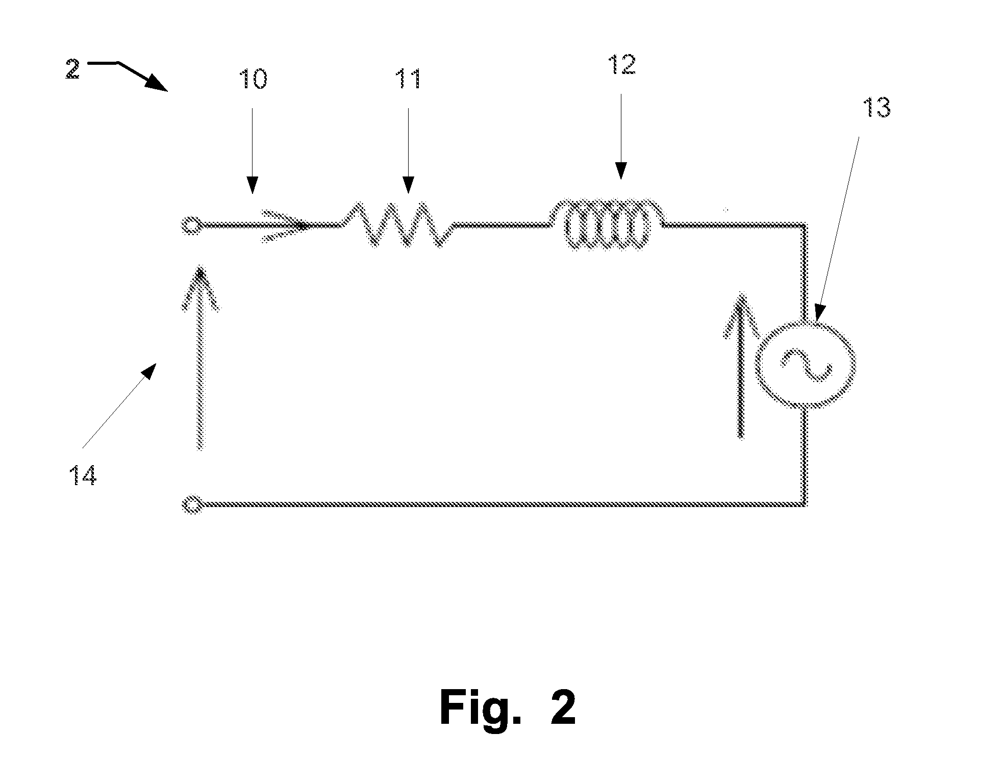
[0037]The movement of the coil within a magnetic field creates a motional electromoti...


PUM


Abstract

A device or method for stabilizing a voice coil is disclosed. The device comprises a voice coil for providing a motive force, and means for measuring a signal from said voice coil related to a motional electromotive force. The device further comprises a unit for controlling an amplification of said signal to create a force in said voice coil in a direction of said motional electromotive force.

Description

BACKGROUND OF THE INVENTION[0001]1. Field of the Invention[0002]This disclosure pertains in general to voice coil motors. More particularly the disclosure relates to controlling a voice coil, such as stabilizing a voice coil for providing a motive force, such as stabilizing a voice coil motor. In particular this relates to voice coil motors for controlling an inspiration or expiration valve for medical ventilators, anaesthesia machines or anaesthesia monitoring.[0003]2. Description of the Prior Art[0004]To control the expiratory pressure (PEEP) a voice coil motor which controls a disc valve is a common solution. In this kind of valve the expiratory pressure is more or less proportional to the force from the voice coil. Also the force from the voice coil is ideally proportional to the current through the windings in the voice coil.[0005]The above model is very simplified. In an actual application, the flow through the valve may vary due to the breathing pattern. This will create a mo...

Claims


Application Information

Patent Timeline
IPC IPC(8): H02P25/02H02K41/035
CPCH02P25/028H02K41/0354A61M16/20F16F15/02F16K31/06A61M16/203A61M16/205H02P25/034
Inventor EKLUND, MATHIASCEWERS, GORAN
Owner SHENZHEN MINDRAY BIO MEDICAL ELECTRONICS CO LTD
Learn More