Image pickup device and camera module

Inactive Publication Date: 2005-12-08
SHARP KK
View PDF5 Cites 18 Cited by
  • Summary
  • Abstract
  • Description
  • Claims
  • Application Information

AI Technical Summary

Benefits of technology

[0040] According to the present invention, since the light receiving unit side of either the device body unit or the device substrate is covered by a transmissive electrically conductive member (hereafter simply referred to as a transmissive conductive member), the image pickup device itself is electrically shielded. Further, in order to stabilize a magnetic shield effect, the transmissive conductive member is electrically connected to a ground wiring portion that is made up of a ground electrode and/or its wiring pattern serving as a reference potential unit. By incorporating such an image pickup device into a camera module, it is possible to prevent electric signals inputted to the camera module from the outside such as a mobile phone from exerting a bad influence on the image pickup device by causing noises, as well as to prevent electric signals from a part of the mobile phone or the like other than the camera module from exerting a bad influence on the image pickup device by causing noises. Further, it is possible to prevent electric signals from the camera module from exerting a bad influence on the signals of the mobile phone main body and other electric devices existing outside of the mobile phone or the like.
[0041] In addition, by having an arrangement wherein the transmissive conductive member such as a transmissive electrically conductive layer (hereafter simply ref erred to as a transmissive conductive layer) has an opening at least in a signal electrode portion thereof, it is possible to avoid a short circuit that may occur with a charging unit such as the signal wiring portion provided on the surface of the device body unit (the image pickup device substrate). Further, by having an arrangement wherein a transmissive electrically insulating member (hereafter, simply referred to as a transmissive insulating member), such as a transmissive electrically insulating layer (hereafter, simply referred to as a transmissive insulating layer), that has one or more openings in the ground wiring portion to provided, and a transmissive conductive member such as a transmissive conductive layer is fur

Problems solved by technology

In the case where the conventional cameral module 10 configured as described above is used in a mobile phone with a camera, when the camera module 10 receives electric signals from the mobile phone main body other than the camera part and electric signals from electric devices other than the mobile phone, some problems arise; for example, the image quality of a photographed image becomes low and/or the camera itself has a malfunction.
Further, when electric signals from the camera module 10 (mainly from the image pickup device unit) goes to the outside, those electric signals may exert a bad influence on other electric devices causing noises and may also cause malfunctions of the electric dev

Method used


Image

  • Image pickup device and camera module
  • Image pickup device and camera module
  • Image pickup device and camera module

Examples


Example

[0069] The following describes first through fourth embodiments of an image pickup device and a camera module in which such an image pickup device is used according to the present invention, with reference to the drawings.

Example

First Embodiment

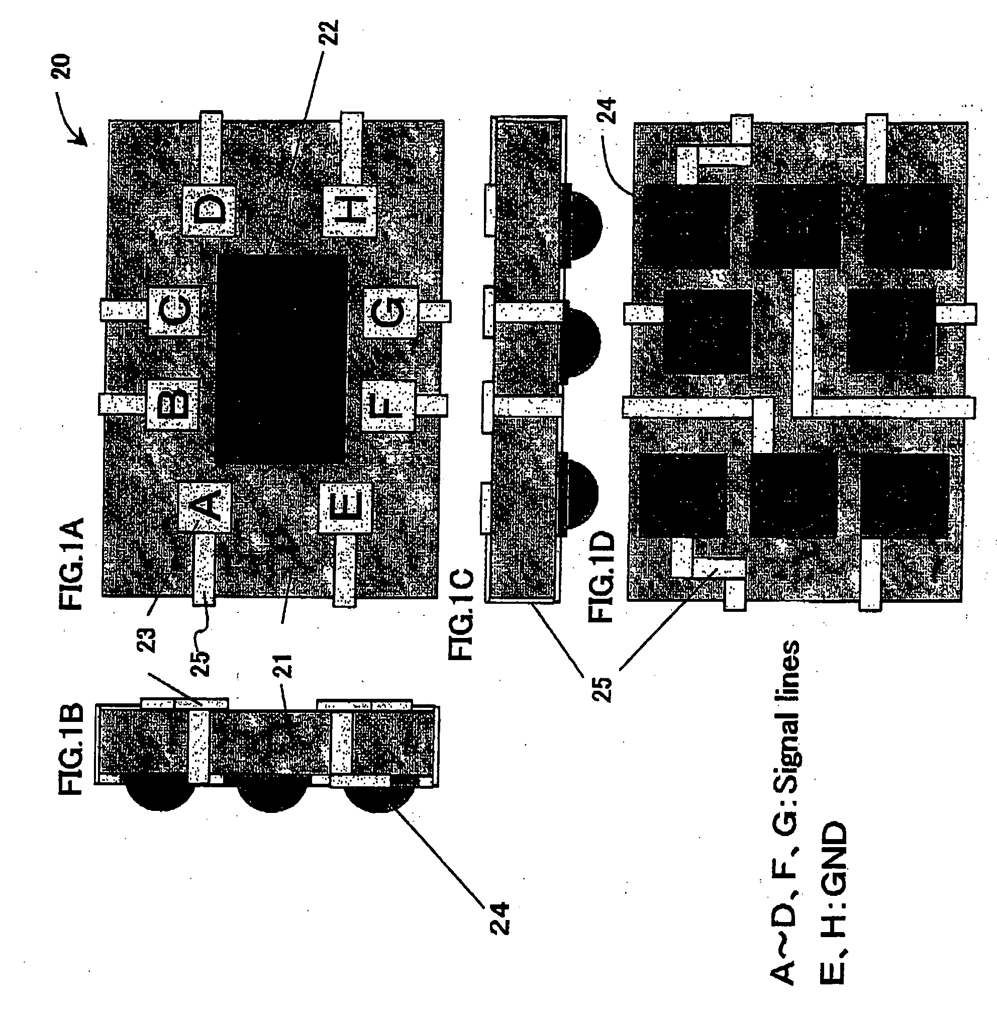
[0070]FIG. 1A is an upper side view that shows an exemplary configuration of an image pickup device according to the first embodiment of the present invention. FIG. 1B is a side view from the left side of FIG. 1A. FIG. 1C is a side view from the bottom side of FIG. 1A. FIG. 1D is a rear side view of FIG. 1A.

[0071] As shown in FIGS. 1A to 1D, the image pickup device 20 is constituted with a CCD image sensor or a CMOS image sensor or the like that converts incident light from the outside (light from an object) into electric signals. A light receiving unit 22 for light from an object is provided in the central part of the surface of the image pickup device body unit (device body unit) 21. The light receiving unit 22 is included in an image pickup unit that forms an image of an object by converting incident light into electric signals (optical signals). Electrodes 23 (bonding pads) are provided around the light receiving unit 22. Bump electrodes 24 (solder bumps) are p...

Example

Second Embodiment

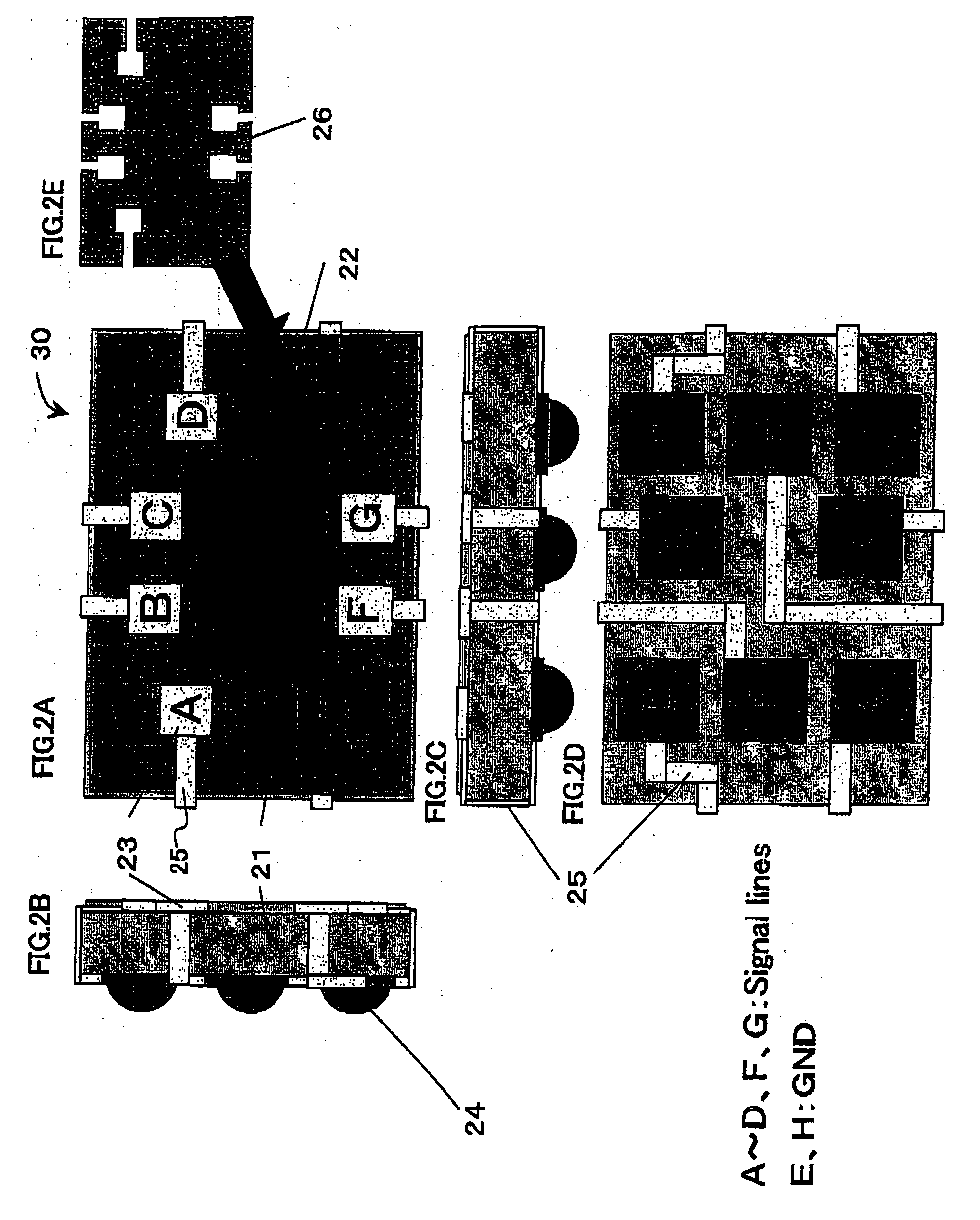
[0090] In the first embodiment, the transmissive conductive layer 26 has one or more openings in the parts that correspond to the conductive units of the signal wiring portion (the electrodes 23; A to D, F, and G, and the wiring pattern 25 that are connected thereto) and the power source wiring portion, out of the electrodes 23 (the bonding pads) and the wiring patterns 25 that are provided on the front surface wide of the image pickup device body unlit 21 (or 21A). In the second embodiment, however, the surface of the image pickup device body unit 21 is covered by a transmissive insulating 27 to be described later that has one or more openings in the parts that correspond to the conductive unit of the ground wiring portion (the electrodes 23; H and K and the wiring patterns 25 that are connected thereto) and further, a transmissive conductive layer 26A to be described later is provided over the transmissive insulating layer 27.

[0091]FIG. 5A is an upper side view ...


PUM


Abstract

The surface of the image pickup device 21 is covered by a transparent conductive member 26 that is made of, for example, a transparent conductive past resin and that is electrically connected to a ground potential GND. By having this arrangement, it is possible to electromagnetically shield the image pickup device 30 itself. The transparent conductive member 26 has one or more openings in the parts that correspond to the conductive unit of the signal wiring portion (the electrodes 23; A to D, F, and G, and the wiring patterns 25 that are connected thereto), out of the electrodes 23 and the wiring patterns 25 provided on the front surface side of the image pickup device body unit 21.

Description

BACKGROUND OF THE INVENTION [0001] 1. Field of the Invention [0002] The present invention relates to image pickup devices such as CMOS image sensors and CCD image sensors used as image pickup units in video cameras, digital still cameras, mobile phones with a camera, portable information terminal devices with a camera and the like, as well as to camera modules including such image pickup devices. [0003] 2. Description of the Related Art [0004] The following describes a conventional camera module of this type, with reference to the drawings. [0005]FIG. 9A is a across sectional view of the main parts to show an exemplary configuration of a conventional camera module. FIG. 9B is a rear side view of the camera module shown in FIG. 9A. FIG. 9A to a arose sectional view at the line A-A′ in FIG. 93. [0006] As shown in FIG. 9A and FIG. 9B, a camera module 10 includes a lens cap 1, a lens 2, a lens barrel 3 that holds the lens 2, an IR (infrared ray) cut filter 4, a camera case 5 that holds ...

Claims


Application Information

Patent Timeline
IPC IPC(8): H01L27/14G03B17/02H01L27/146H01L31/0216H01L31/0232H04N5/225H04N5/335H04N5/357H04N101/00H05K9/00
CPCH04N5/2257H01L27/14618H01L2224/13H01L2224/48091H01L2224/48227H04N23/57H01L2924/00014H01L27/146H04N25/00H04N25/60
Inventor TANIDA, YOSHINORIFUKUDA, HIROAKITOJO, YUKIO
Owner SHARP KK
Why Eureka
Try Eureka