This helps you quickly interpret patents by identifying the three key elements:
Problems solved by technology
Method used
Benefits of technology
Benefits of technology
The patent describes a robot that can collect dust on its own. This robot has a versatile battery pack that can be used in different models of the robot. The motor for the robot's fan is placed between two battery packs, which results in a well-balanced design. This design helps to save money and time.
Problems solved by technology
Such a design necessitates the preparation (design and manufacture) of batteries that differ by model, which incurs costs as well as time and labor to manage the variety of battery designs.
In addition, because known floor cleaning devices utilize only one battery (or one set of battery cells connected in series and / or in parallel), the continuous usage (run) time is relatively short, which means that the charging (recharging) frequency is high.
Furthermore, the center of gravity is offset by the arrangement of the battery, and consequently some designs can not stably move (travel along the floor) during a floor cleaning operation.
Method used
Image
Click on the blue label to locate the original text in one second.
Reading with bidirectional positioning of images and text.
Examples
first embodiment
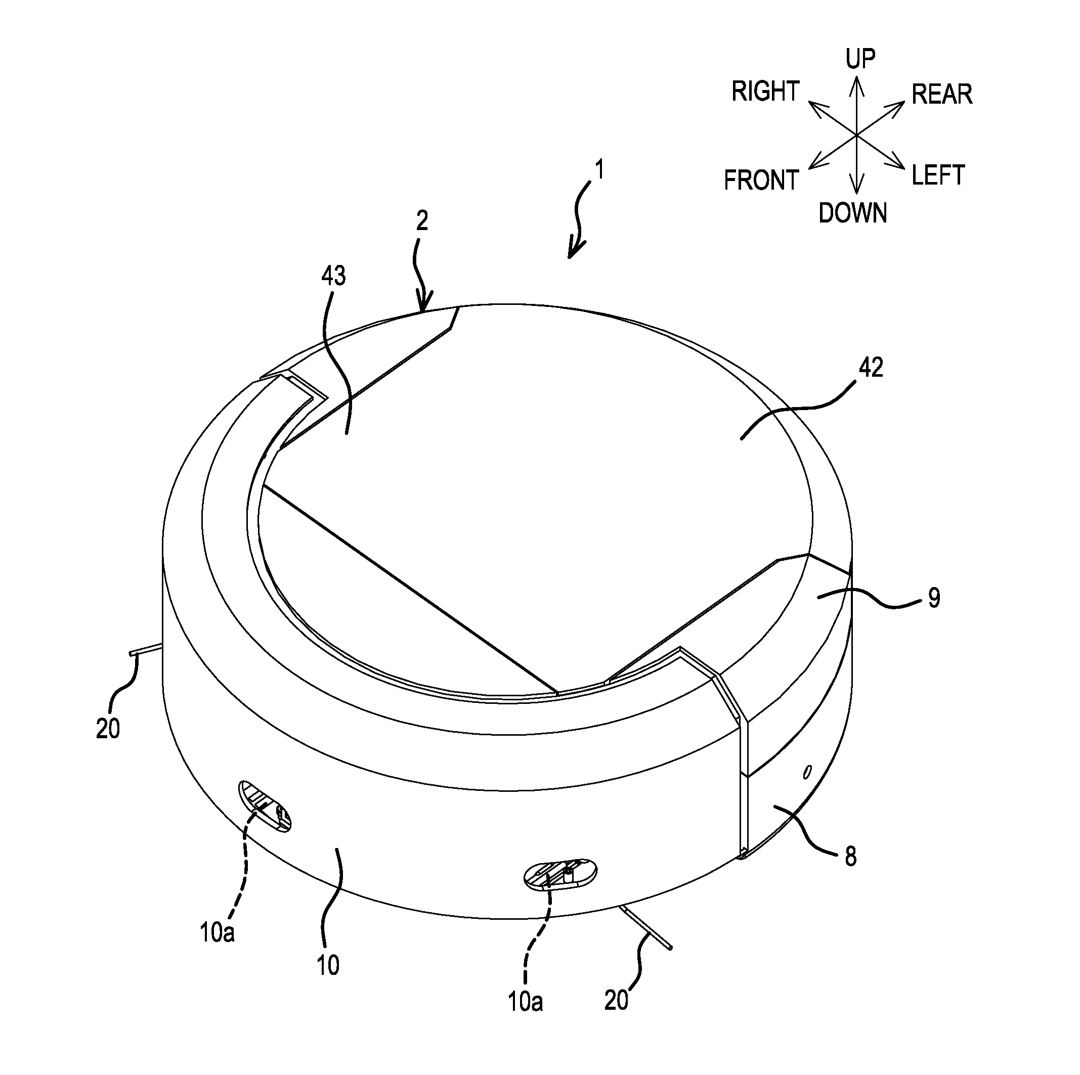
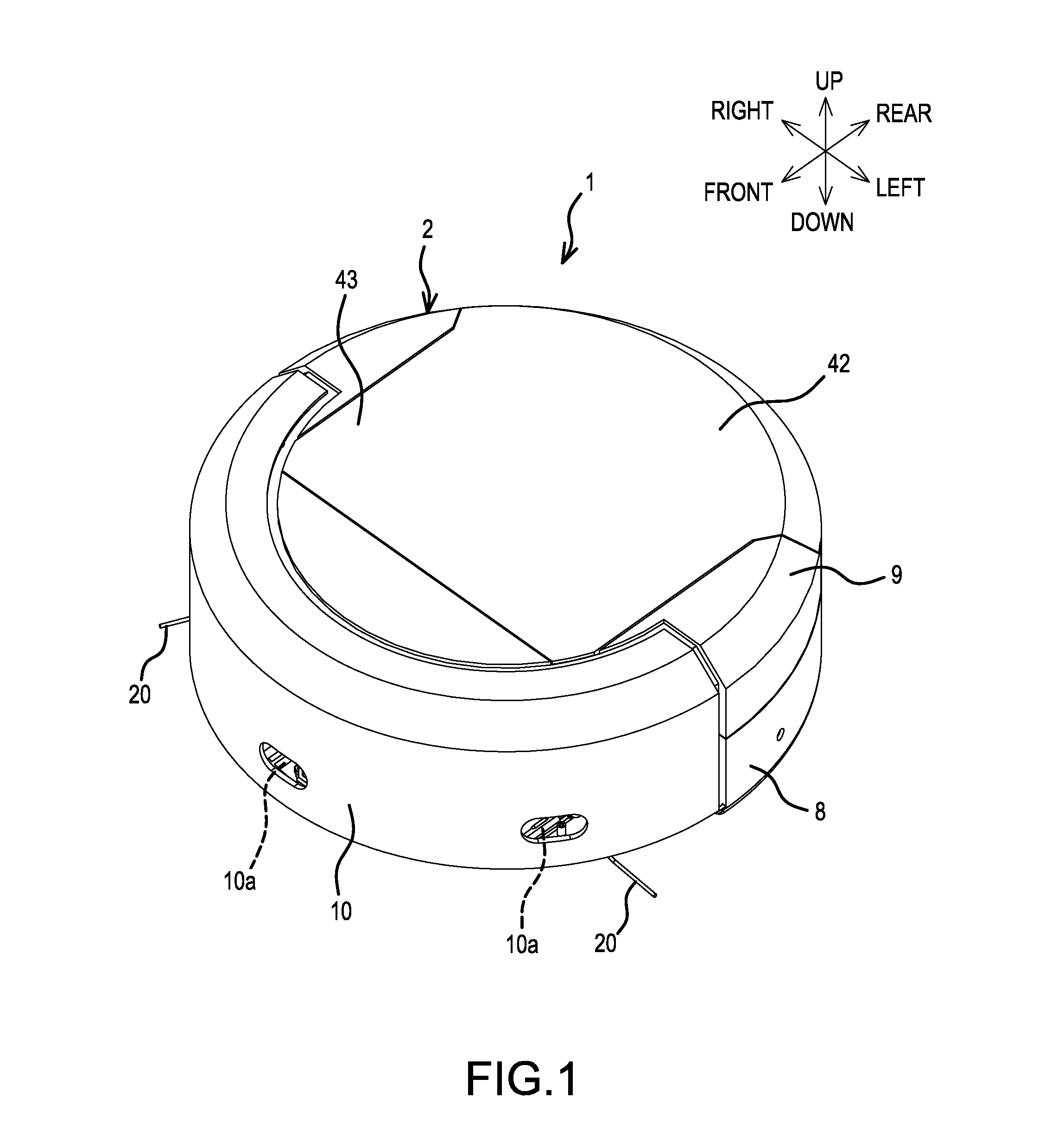
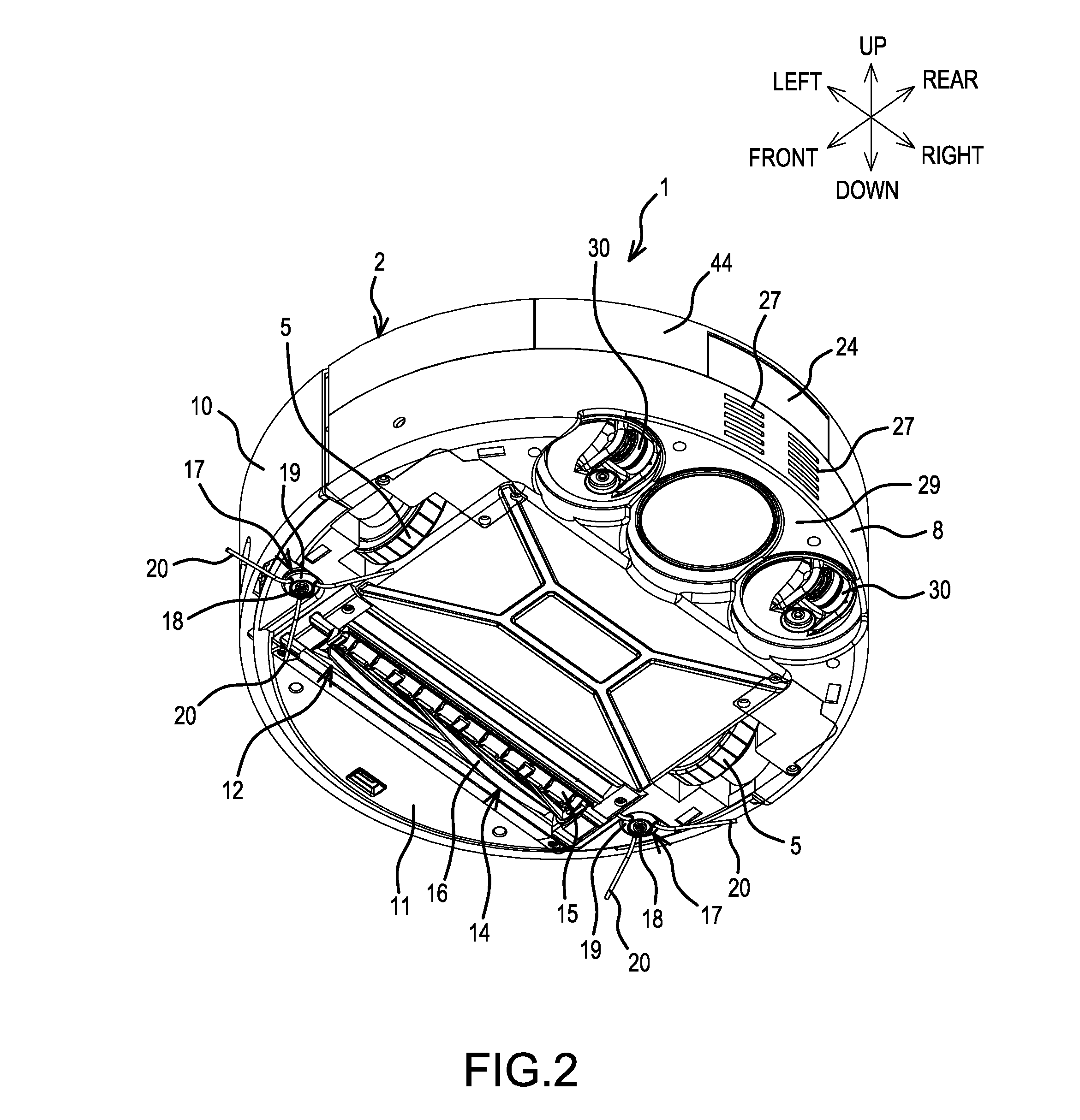
[0035]As shown in FIGS. 1-5, a self-propelled, dust-collecting robot 1 (hereinbelow, simply called “dust-collecting robot”) according to the present teachings comprises, inside a main-body part (chassis) 2 that has a circular box (circular cylindrical) shape in plan view: left and right batteries (battery packs) 3; left and right electric motors 4, 4 that are respectively powered by the left and right batteries 3; a pair of left and right wheels 5, each of which can be independently rotated forwardly and reversely by its corresponding motor 4; a dust-collection motor 6 disposed between the batteries 3; and a dust-collection box 7. Lower portions of the wheels 5, 5 respectively protrude downward from (through) a bottom surface of the main-body part 2. The dust-collection motor 6 and the dust-collection box 7 constitute a dust-collection unit.
[0036]Dust-collecting robots 1 according to the present teachings are also known in the art as an autonomous floor-cleaning robot, autonomous fl...
embodiment 2
[0095]3. The self-propelled, dust-collecting robot according to above-mentioned embodiment 2, wherein a cover body, which is capable of simultaneously exposing the dust-collection box and the battery, is provided on the main-body part.
[0096]4. The self-propelled, dust-collecting robot according to above-mentioned embodiment 1 or 2, wherein the battery is provided with a pair of rails for coupling to a power tool; and an engaging portion, to which the rails can couple from an up-down direction, is formed on the main-body part.
embodiment 4
[0097]5. The self-propelled, dust-collecting robot according to above-mentioned embodiment 4, wherein the engaging portion is provided such that, in plan view, it faces the outer side of the main-body part.
[0098]6. The self-propelled, dust-collecting robot according to any of the above-mentioned embodiments, wherein a plurality of the batteries is provided.
[0099]7. A battery capable of being used in a self-propelled, dust-collecting robot, a portable cleaner, and a tank-type dust collector with castors.
[0100]8. A battery capable of being used in a self-propelled, dust-collecting robot, a power tool that drives a tool accessory using a motor, and electrical equipment wherein a motor is not used.
[0101]9. A self-propelled, dust-collecting robot, comprising a main-body part; a dust-collection unit provided on the main-body part; and a plurality of batteries disposed inside the main-body part.
[0102]10. A self-propelled, dust-collecting robot, comprising a main-body part; a dust-collectio...
PUM
Abstract
A self-propelled, dust-collecting robot includes a chassis, an electric motor supported by the chassis, and first and second rechargeable battery packs disposed inside the chassis for supplying current to the electric motor. First and second castors are respectively disposed immediately underneath the first and second battery packs. Each of the battery packs has a pair of rails that respectively slide into and engage with complementary guide rails coupled to the chassis. A dust-collection box is removably disposed within the chassis. A dust-collection motor rotates a suction fan that is in fluid communication with the dust-collection box. At least one rotatable brush sweeps dust towards a suction port in fluid communication with the dust-collection box.
Description
CROSS-REFERENCE[0001]The present application claims priority to Japanese patent application serial numbers 2014-205005 and 2014-205006, both filed on Oct. 3, 2014, the contents of which are incorporated fully herein by reference.TECHNICAL FIELD[0002]The present invention relates to a self-propelled, dust-collecting robot or autonomous floor cleaning robot powered by one or more rechargeable battery packs designed for power tools.BACKGROUND ART[0003]Self-propelled sweepers or robotic vacuum cleaners that collect dust from the surface of a floor are known and include a built-in motor that rotationally drives its wheels. As disclosed, for example, in Japanese Unexamined Utility Model Application Publication No. H5-88472, such a sweeper may comprise a rotary brush that is rotated by the drive of a motor and is disposed forward of a suction port. The sweeper gathers or sweeps up dust from the surface of the floor using the rotary brush.SUMMARY OF THE INVENTION[0004]Known self-propelled, ...
Claims
Application Information
Patent Timeline
Application Date:The date an application was filed.
Publication Date:The date a patent or application was officially published.
First Publication Date:The earliest publication date of a patent with the same application number.
Issue Date:Publication date of the patent grant document.
PCT Entry Date:The Entry date of PCT National Phase.
Estimated Expiry Date:The statutory expiry date of a patent right according to the Patent Law, and it is the longest term of protection that the patent right can achieve without the termination of the patent right due to other reasons(Term extension factor has been taken into account ).
Invalid Date:Actual expiry date is based on effective date or publication date of legal transaction data of invalid patent.

