
Voltage generating circuit

a voltage generation circuit and voltage technology, applied in the direction of electric variable regulation, process and machine control, instruments, etc., can solve the problems of increasing circuit costs, ldo regulators and pwm circuits may not meet the requirements

Inactive Publication Date: 2016-04-07
M31 TECH
View PDF10 Cites 73 Cited by
  • Summary
  • Abstract
  • Description
  • Claims
  • Application Information

AI Technical Summary

Benefits of technology

The present invention provides a switching-capacitor type of voltage generating circuit that addresses the problem of voltage fluctuations caused by changes in input signals. The circuit includes a first driving unit, a first switch, a first compensating capacitor, and a second switch. The first driving unit charges or discharges power based on the input signal, and the first switch connects the second voltage terminal to the first compensating terminal based on the input signal. The first compensating capacitor is connected between the first compensating terminal and the third voltage terminal, and the second switch connects the first compensating terminal to the fourth voltage terminal based on the input signal. This circuit design helps to stabilize the voltage and reduce fluctuations.

Problems solved by technology

However, the employment would cause increase of circuit costs and the low-dropout (LDO) regulator and pulse-width modulation (PWM) circuit may have the integrated circuit to operate at a limited speed and with a stability issue.
For example, when a circuit is utilized to process a serial data stream at a high speed, such as at a speed higher than 1 GHz, the LDO regulator and the PWM circuit may not meet the requirement.

Method used


Image

  • Voltage generating circuit
  • Voltage generating circuit
  • Voltage generating circuit

Examples


Embodiment Construction

[0022]Illustrative embodiments are now described. Other embodiments may be used in addition or instead. Details that may be apparent or unnecessary may be omitted to save space or for a more effective presentation. Conversely, some embodiments may be practiced without all of the details that are disclosed.

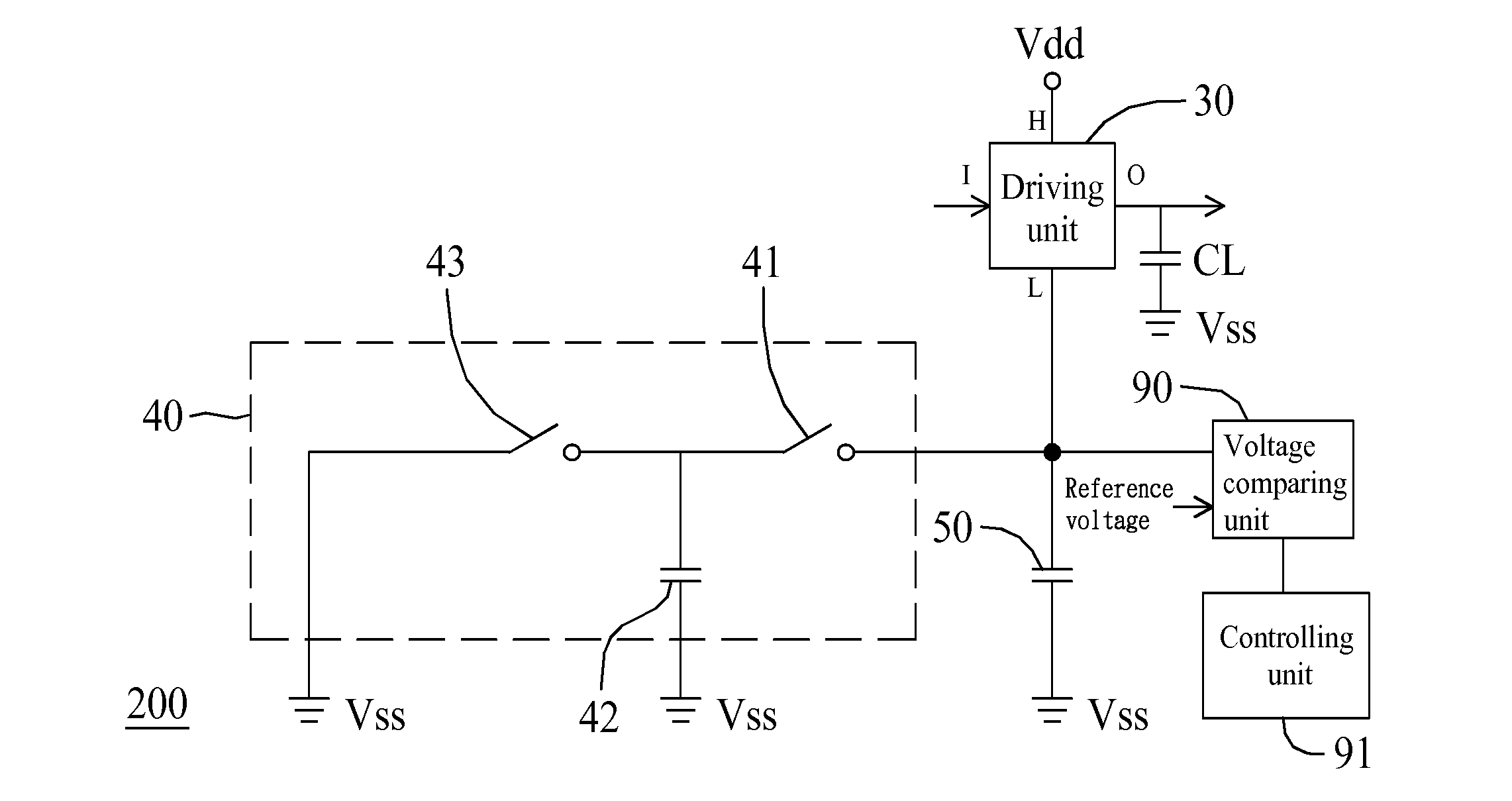
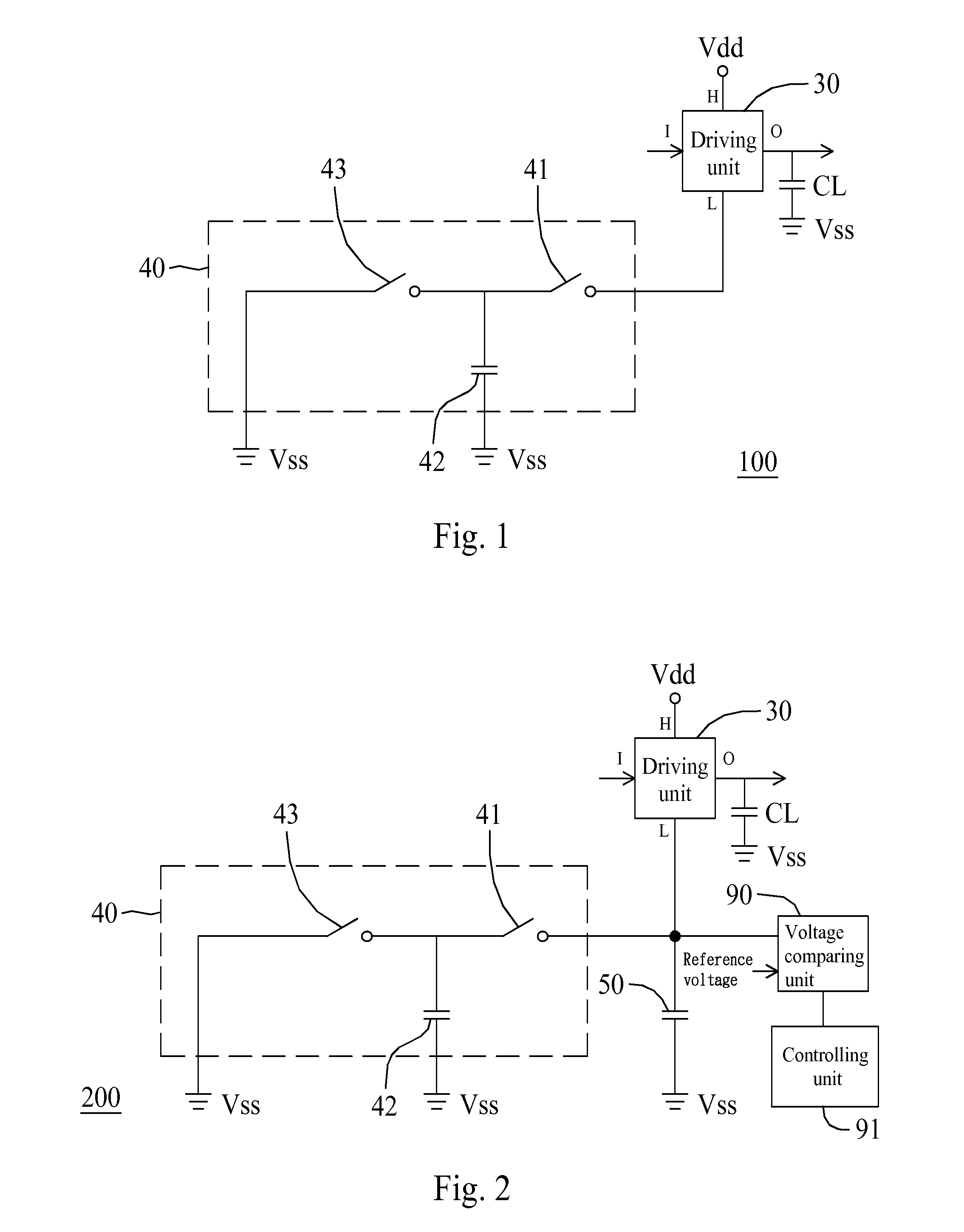
[0023]FIG. 1 shows a circuit diagram of a voltage generating circuit in accordance with an embodiment of the present invention. Referring to FIG. 1, a voltage generating circuit 100 includes a first driving unit 30, a first switch 41, a first compensating capacitor 42 and a second switch 43. The first driving unit 30 has a first input terminal I and a first output terminal O, wherein the first input terminal I is configured to receive a first input signal. When the first input signal is at a first logic level, such as logic level of 0, power is configured to be charged from a first voltage terminal H, such as Vdd terminal, to the first output terminal O. When the first input signal...


PUM


Abstract

A voltage generating circuit includes: (1) a driving unit having an input terminal and an output terminal, wherein the input terminal is configured to receive an input signal, wherein when the input signal is at a first logic level, power is configured to be charged from a first voltage terminal to the output terminal, and when the input signal is at a second logic level, power is configured to be discharged from the output terminal to a second voltage terminal; (2) a first switch configured to couple the second voltage terminal to a capacitance-compensating terminal based on the input signal; (3) a compensating capacitor configured to be coupled between the capacitance-compensating terminal and a third voltage terminal; and (4) a second switch configured to couple the capacitance-compensating terminal to a fourth voltage terminal based on the input signal.

Description

RELATED APPLICATION[0001]This application claims priority to TW application No. 103134588, filed on Oct. 3, 2014, all of which is incorporated herein by reference in their entirety.BACKGROUND OF THE DISCLOSURE[0002]1. Field of the Disclosure[0003]The disclosure relates to a voltage generating circuit, and more particularly, to a voltage generating circuit configured to be compensated by a capacitor.[0004]2. Brief Description of the Related Art[0005]An integrated circuit may employ a low-dropout (LDO) regulator or a pulse-width modulation (PWM) circuit to generate an adequate voltage. However, the employment would cause increase of circuit costs and the low-dropout (LDO) regulator and pulse-width modulation (PWM) circuit may have the integrated circuit to operate at a limited speed and with a stability issue. For example, when a circuit is utilized to process a serial data stream at a high speed, such as at a speed higher than 1 GHz, the LDO regulator and the PWM circuit may not meet...

Claims


Application Information

Patent Timeline
IPC IPC(8): G05F1/56
CPCG05F1/56
Inventor FAN, HUNG-CHENG
Owner M31 TECH
Learn More