Capillary tube for a packaged terminal air conditioner unit

a packaged terminal and air conditioner technology, applied in mechanical equipment, refrigeration components, light and heating equipment, etc., can solve the problems of difficult utilizing electronic expansion valves within packaged terminal air conditioner units, bulky electronic expansion valves, and limited selection of sealed system components, etc., to increase the pressure of refrigerant

Inactive Publication Date: 2016-04-14
HAIER US APPLIANCE SOLUTIONS INC
View PDF8 Cites 1 Cited by
  • Summary
  • Abstract
  • Description
  • Claims
  • Application Information

AI Technical Summary

Benefits of technology

[0006]In a first exemplary embodiment, a packaged terminal air conditioner unit is provided. The packaged terminal air conditioner unit includes a casing that extends between an exterior side portion and an interior side portion. A compressor is positioned within the casing. The compressor is operable to increase a pressure of a refrigerant. An interior coil is positioned within the casing at the interior side portion of the casing. An exterior coil is positioned within the casing at the exterior side portion of the casing. A reversing valve is in fluid communication with the compressor in order to receive compressed refrigerant from the compressor. The reversing valve is configured for selectively directing the compressed refrigerant from the compressor to either the interior coil or the exterior coil. A capillary tube extends between the interior coil and the exterior coil in order to direct refrigerant between the interior coil and the exterior coil. The capillary tube includes means for adjusting a restriction on a flow of refrigerant through the capillary tube depending upon a direction of the flow of refrigerant through the capillary tube.

Problems solved by technology

Due to space constraints within the casing, selection of sealed system components for packaged terminal air conditioner units can be limited.
For example, electronic expansion valves can be bulky and occupy a large volume within the casing.
Thus, utilizing electronic expansion valves within packaged terminal air conditioner units can be difficult despite functional advantages provided by electronic expansion valves.
Electronic expansion valves can also be costly.

Method used


Image

  • Capillary tube for a packaged terminal air conditioner unit
  • Capillary tube for a packaged terminal air conditioner unit
  • Capillary tube for a packaged terminal air conditioner unit

Examples


Embodiment Construction

[0024]Reference now will be made in detail to embodiments of the invention, one or more examples of which are illustrated in the drawings. Each example is provided by way of explanation of the invention, not limitation of the invention. In fact, it will be apparent to those skilled in the art that various modifications and variations can be made in the present invention without departing from the scope or spirit of the invention. For instance, features illustrated or described as part of one embodiment can be used with another embodiment to yield a still further embodiment. Thus, it is intended that the present invention covers such modifications and variations as come within the scope of the appended claims and their equivalents.

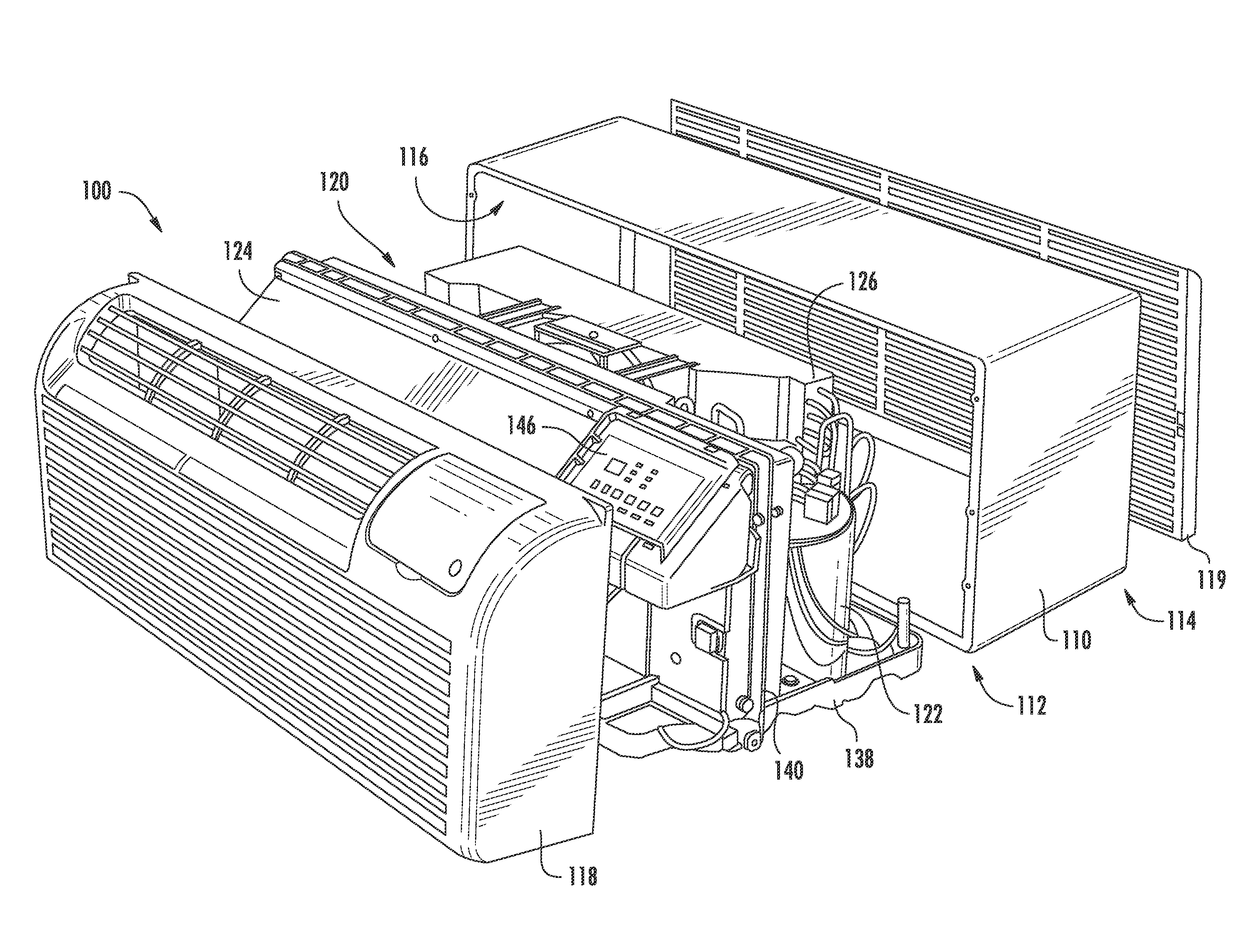
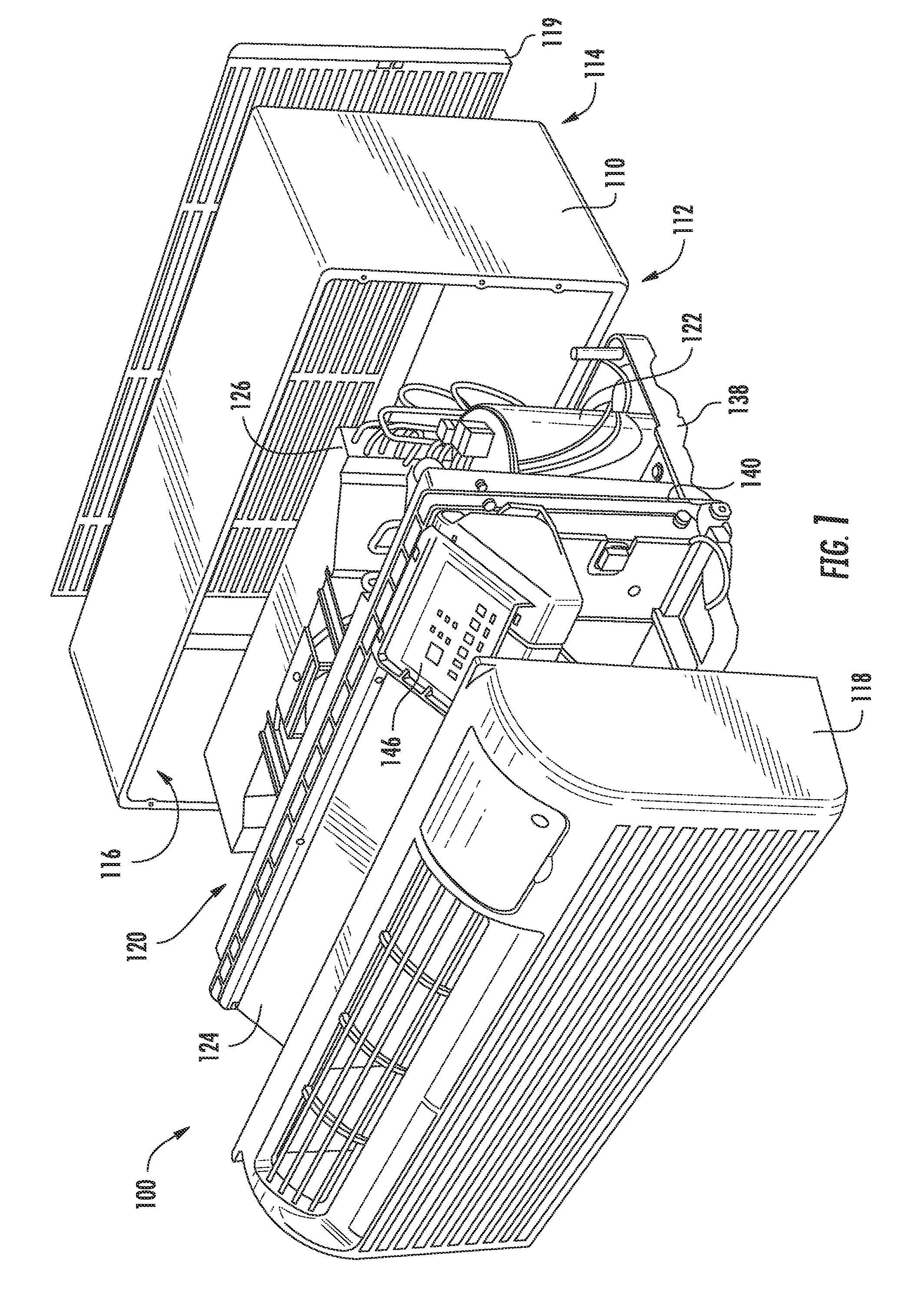
[0025]FIG. 1 provides an exploded perspective view of a packaged terminal air conditioner unit 100 according to an exemplary embodiment of the present subject matter. Packaged terminal air conditioner unit 100 is operable to generate chilled and / or heated a...


PUM


Abstract

A capillary tube for a heat pump system, such as a packaged terminal air conditioner unit, includes features for adjusting a restriction on a flow of refrigerant through the capillary tube depending upon a direction of the flow of refrigerant through the capillary tube. A related packaged terminal air conditioner unit is also provided.

Description

FIELD OF THE INVENTION[0001]The present subject matter relates generally to heat pump systems, such as packaged terminal air conditioner units, and capillary tubes for the same.BACKGROUND OF THE INVENTION[0002]Certain heat pump systems include a sealed system for chilling and / or heating air with refrigerant. The sealed systems generally include a throttling device for restricting a flow of refrigerant between an outdoor coil and an indoor coil of the sealed system. Various throttling devices are available, including capillary tubes, J-T valves, electronic expansion valves, etc. Electronic expansion valves can offer functional advantages over other throttling devices. In particular, electronic expansion valves can be adjusted to vary the restriction on refrigerant flowing through the electronic expansion valves.[0003]Packaged terminal air conditioner units generally include a casing and a sealed system. Due to space constraints within the casing, selection of sealed system components...

Claims


Application Information

Patent Timeline
Patent Type & Authority Applications(United States)
IPC IPC(8): F25B41/06F25B41/04
CPCF25B41/046F25B41/067F25B2341/062F25B41/375F25B41/38
Inventor JUNGE, BRENT ALDENKEMPIAK, MICHAEL JOHNHITZELBERGER, JOEL ERIK
Owner HAIER US APPLIANCE SOLUTIONS INC
Why Eureka
Try Eureka