
Easy glide abrasive tip for a microdermabrasion device

a microdermabrasion and abrasive tip technology, applied in the field of microdermabrasion devices, can solve the problems of reducing effectiveness, reducing effectiveness, and being difficult to move over the face, and achieve the effects of reducing lateral force, reducing lateral force, and facilitating gliding over the skin

Inactive Publication Date: 2016-04-21
KONINKLJIJKE PHILIPS NV
View PDF8 Cites 13 Cited by
  • Summary
  • Abstract
  • Description
  • Claims
  • Application Information

AI Technical Summary

Benefits of technology

The patent is about a device that uses a vacuum to remove skin layers and has a balance between abrasion effectiveness and ease of use. The device has a gliding zone that can be stationary or move with vibration. The device can also have a rotating microdermabrasion zone. The main technical effect is to improve the performance and comfort of the device when applying abrasion to the skin.

Problems solved by technology

Prior art devices may not have an optimized balance between abrasion effectiveness and easiness in use.
Lowering a vacuum in device allows the user to move with less force over the skin but reduces effectiveness.
Increasing the vacuum may improve effectiveness, but may make it more difficult to move over the face and / or may reduce application comfort.
Further, increasing the friction / abrasion of the abrasive texture may reduce application comfort.
Likewise, reducing the friction / abrasion of the abrasive texture may improve gliding over the face, but may reduce effectiveness.
Hence, this zone, especially the ring, may have abrasive roughness.

Method used


Image

  • Easy glide abrasive tip for a microdermabrasion device
  • Easy glide abrasive tip for a microdermabrasion device
  • Easy glide abrasive tip for a microdermabrasion device

Examples


Embodiment Construction

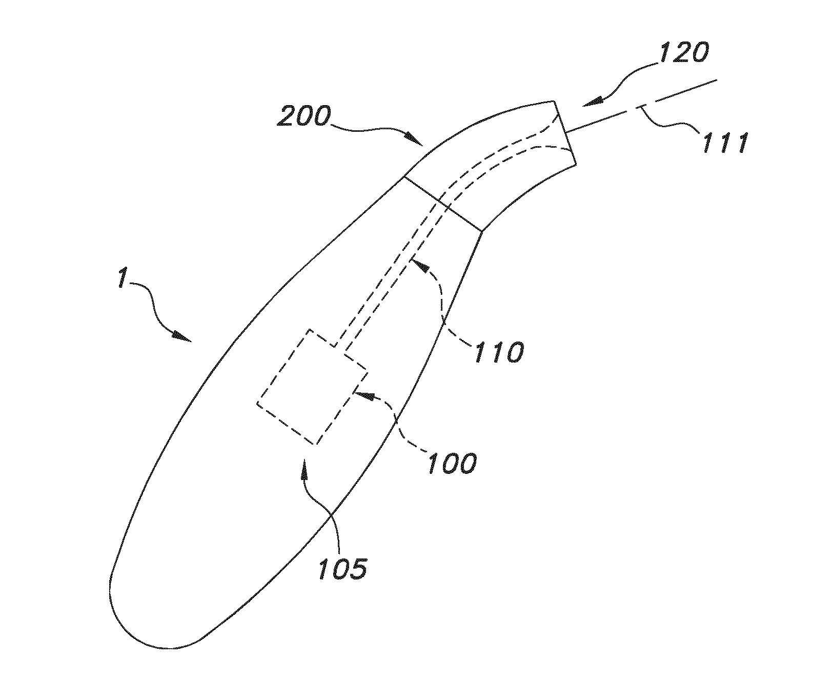
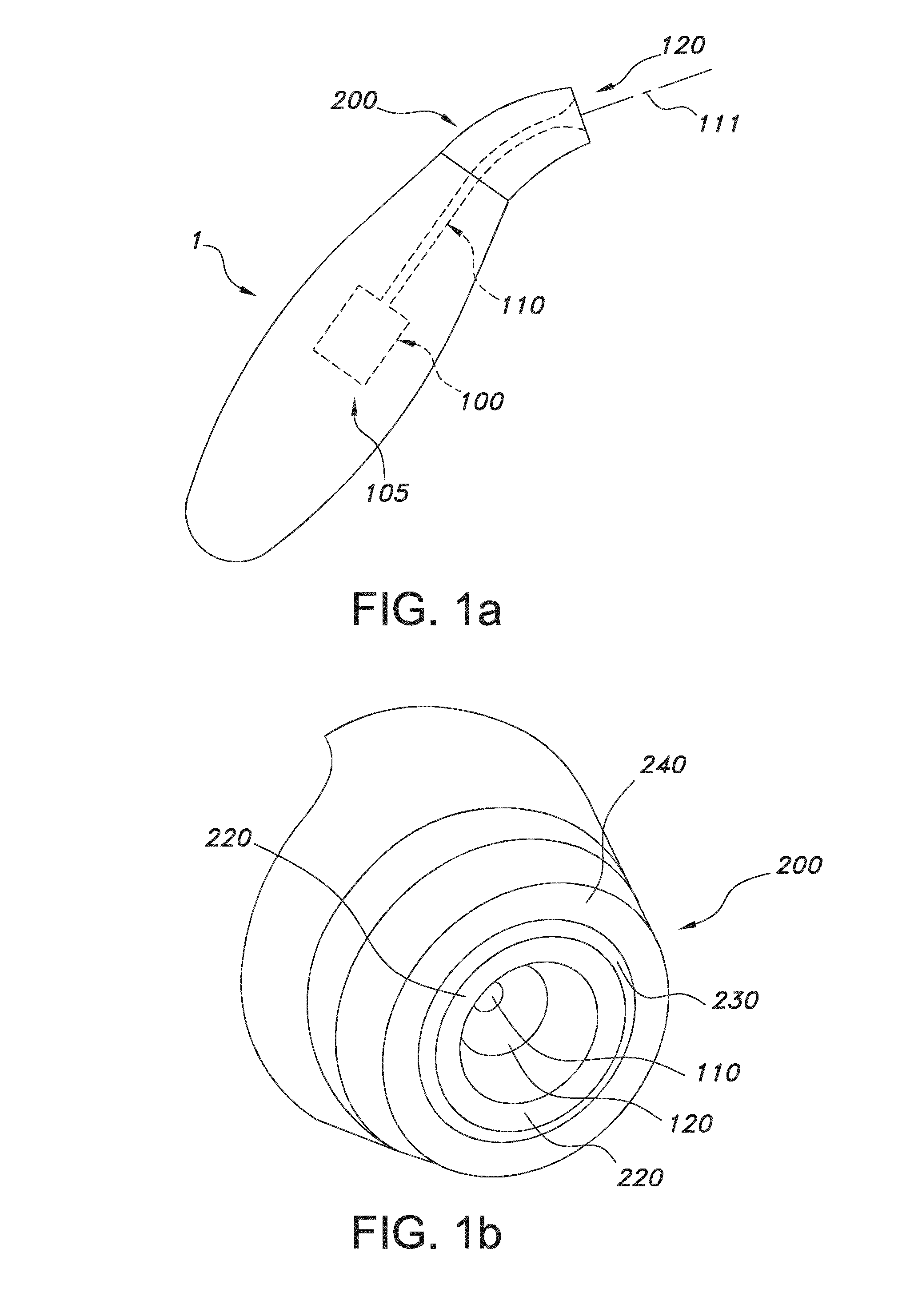
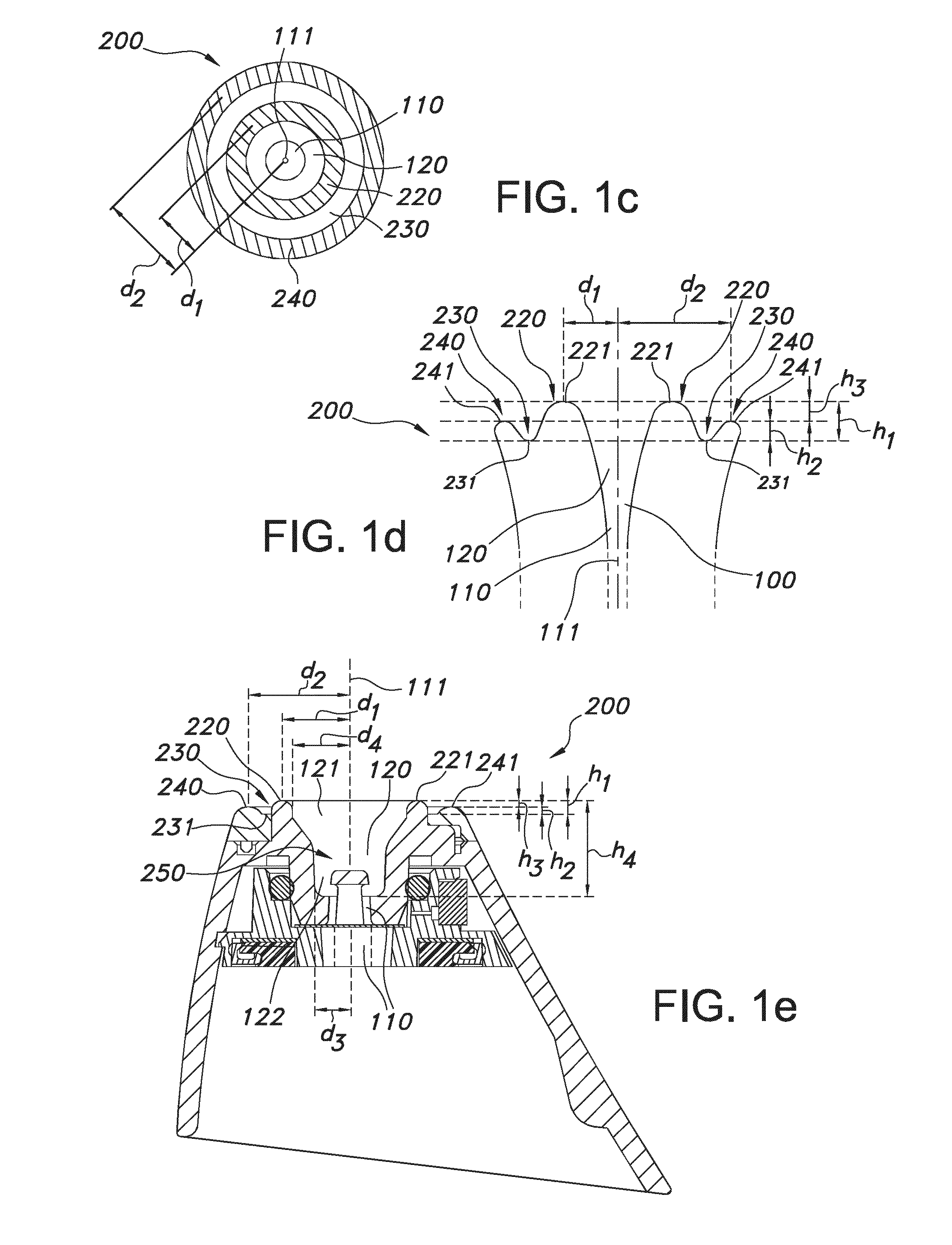
[0049]FIGS. 1a and 1b schematically depicts an embodiment of a microdermabrasion device 1. This device 1 comprises a vacuum system 100, with a pump 105 and a channel 110. Further, this device 1 comprises a device tip 200. Pump 105 can suck air into the channel 110. Channel 110 has a channel inlet 120 at the device tip 200. In other words, the device tip has a channel inlet 120 which is part of the channel 110 of the vacuum system 100. The channel inlet 120 is (perimetrically) surrounded by a channel rim 220. This channel rim 220 may facilitate gliding of the device tip 200 over a skin (not shown). The device tip 200 further comprises a microdermabrasion zone 240 configured remote from the channel inlet 120 with a recession 230 configured between the microdermabrasion zone 240 and the channel rim 220. FIG. 1b schematically depicts in 3D view by way of example an embodiment of a device tip 200 having a ring-shaped channel rim 220, recession 230 and abrasion zone 240, all (perimetrical...


PUM


Abstract

The invention provides a microdermabrasion device comprising a vacuum system and a device tip, wherein the vacuum system comprises a channel with a channel inlet at the device tip, wherein the channel inlet is surrounded by a channel rim which facilitates gliding of the device tip over a skin, and wherein the device tip comprises a microdermabrasion zone configured remote from the channel inlet with a recession configured between the microdermabrasion zone and the channel rim.

Description

FIELD OF THE INVENTION[0001]The invention relates to a microdermabrasion device, to a method for the controlled removal of at least part of the stratum corneum with such device, as well as to specific uses of such device.BACKGROUND OF THE INVENTION[0002]Microdermabrasion devices are known in the art. U.S. Pat. No. 6,241,739 describes for instance a treatment tool and tissue collection system, for removal of outer layers of skin to provide a revitalized, fresh skin surface, and a method of using same, comprising an abrasive tipped tool mounted on the end of a tube, said tube being connected to a source of vacuum. The vacuum aids in maintaining intimate contact between the abrasive tip and the skin during the treatment process and transports the removed tissue to a collection container.[0003]Especially, this document describes a device for removing portions of the outer layers of skin comprising a source of a vacuum, and a tube with an abrasive treatment tip thereon for dislodging cel...

Claims


Application Information

Patent Timeline
IPC IPC(8): A61B17/54
CPCA61B17/54A61B2017/320004A61B2217/005A61B17/32A61H9/0057A61B2017/308A61B2017/00561A61B2017/00761A61H7/005A61H7/008A61H2201/0107
Inventor JANSEN, MARJOLEIN YVONNEBRUIN, EELCO HENRICUS MARIA
Owner KONINKLJIJKE PHILIPS NV
Learn More